
A Human Power Conversion System Based on Children’s Play
January 27, 2021
Anchor Retaining Walls Deep for Many Floors
January 27, 2021
In the intricate dance of electromagnetic waves, the design of two-layer spiral filters unveils its symphony through the precision of SONNET Software, orchestrating a harmonious convergence of functionality and elegance.
Outline
- Introduction
- Electromagnetic Waves
- Design of a Microwave Filter
- Coupling Coefficient
- Conclusion
- References
In the fast-paced landscape of RF (Radio Frequency) filter design, staying at the forefront of innovation is essential to address the ever-evolving demands of modern communication systems. This blog delves into the intricacies of a cutting-edge methodology employed in the design of two-layer spiral filters, harnessing the power of advanced Electromagnetic CAD tools. Specifically, we'll shine a spotlight on the capabilities offered by SONNET software, a state-of-the-art tool in the realm of electromagnetic simulation and design. So, buckle up for a journey into the world of RF engineering, where precision and efficiency converge to shape the future of communication technologies.
Now, let's embark on a comprehensive exploration that unveils the unique features and methodologies inherent in the design process of two-layer spiral filters. Through the lens of SONNET software, we'll dissect the complexities of this advanced Electromagnetic CAD tool, showcasing how it empowers engineers in meeting the intricate challenges posed by modern RF filter design. Join us as we unravel the synergies between precision and efficiency in this dynamic field, where each innovation contributes to the seamless evolution of communication systems.


Introduction
Inductors and capacitors are fundamental components within resonating circuits, each featuring two terminals. The voltage across these terminals correlates with the current flowing through them. The distinctive characteristic of any inductor or capacitor lies in its proportionality coefficient. These elements represent and delineate the impact of magnetic fields on circuit variables. The stored energy within these magnetic fields influences current and voltage, making inductor components instrumental in modelling these effects.
The relationship of an inductor with the voltage across its terminals and the passing current can be defined as:
(1)
Where VL= Voltage across the terminals of the inductor
iL= current through the inductor
LX = Inductance of inductor
The unit H (Henry) equals Vs/A (Volt-second per Ampere).
The relationship between a capacitor with the voltage across its terminals and the passing current can be defined as:
(2)
Where VC= Voltage across the terminal of the capacitor
iC= current through the capacitor
CX = Capacitance
The unit F (Farad) is equal to As/V (Ampere-second per Volt and F = C/V)
Electromagnetic Waves
Microwaves encapsulate electromagnetic waves within the frequency range of 300 MHz to 300 GHz, with wavelengths spanning 1 m to 1 mm in free space. The subset of waves between 30 and 300 GHz is called millimeter waves, given their millimeter-scale wavelengths (1–10 mm). Beyond this domain lies the infrared spectrum, characterized by electromagnetic waves with wavelengths ranging from 1 µm to 1 mm. Further along the spectrum, we encounter the visible optical spectrum, ultraviolet spectrum, and x-rays, surpassing the infrared region.
The radio frequency spectrum is situated just below the microwave frequency spectrum, with the demarcation between the two often considered arbitrary. Technological applications dictate the frequency range, with microwaves finding utility in radar, communication, sensing, radio astronomy, medical instrumentation, and navigation within the frequency range of 300 kHz to 300 GHz. Subsequently, the frequency spectrum is subdivided into various sub-bands and filters play a pivotal role in diverse microwave applications. Filters facilitate the separation and combination of different frequencies, allowing the confinement or selection of radio frequency signals within assigned spectral limits.
Emerging technologies, notably wireless communication, pose challenges to microwave filters due to their demands for smaller size, lower cost, stringent requirements, and enhanced performance. Microwave filter design, incorporating distributed and lumped elements, hinges on specific specifications and requirements. Various transmission line structures, such as coaxial lines, micro-strips, or waveguides, are considered for filter design applications. The field has witnessed rapid development due to advancements in fabrication technologies and novel materials like MEMS (micro-electro-mechanical systems), MMIC (monolithic microwave integrated circuits), LTCC (low-temperature co-fired ceramics), and high-temperature superconductors. Further, advancements in computer-aided design tools, including full-wave electromagnetism simulators, have revolutionized filter design.
In microwave engineering, filter systems emerge as crucial building blocks. These systems enable the rejection, selection, combination, or separation of signals at different frequencies within microwave equipment. While the physical implementations of these systems may vary for different frequencies, the underlying circuit network topology remains consistent across all applications (Matthaei et al., 1964).
Direct measurement of currents and voltages using conventional ammeters and voltmeters is unfeasible at microwave frequencies. Consequently, current and voltage are not primary measures for electrical excitations at these frequencies. However, the operation of microwave networks can be aptly described in terms of filter networks, facilitating impedance, current, and voltage measurements and optimizing the application of low-frequency network concepts (Hong and Lancaster, 2001).
Microstrip Lines
Microstrip lines are transmission lines used in high-frequency electronics and microwave engineering. Consisting of a conductor strip separated from a ground plane by a dielectric substrate, microstrip lines offer compact and lightweight solutions for signal propagation. They are used widely in various applications, including RF and microwave circuit designs, antennas, and communication systems. The advantages of microstrip lines include ease of fabrication, cost-effectiveness, and the ability to integrate with other components on a single substrate. Their design flexibility makes them popular for achieving controlled impedance and efficient signal transmission in miniaturized electronic devices.
Structure
Waves
The microstrip structure is characterized by two media that create a homogeneous composition: air above and dielectric below. The microstrip has not been found to support pure TEM waves due to its non-homogeneous nature. The lack of support can be attributed to the transverse component of the pure TEM wave. This non-supportive nature is influenced by material properties such as permeability and permittivity, which, in turn, determine the propagation velocity of the microstrip (Hong and Lancaster, 2001)
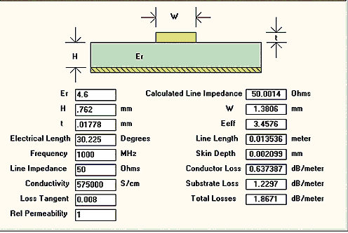
Fig 1: Example Microwave stripline structure
Design of a Microwave Filter
The design process follows an iterative cycle, as proposed by Huang and Xiong in 2003. Early designs are simulated, and resonant frequencies and real coupling coefficients are obtained through curve fitting. These values are then compared with desired ones, leading to micro-strip lengths and spacing adjustments. The iterative nature of the process allows for gradual refinement based on estimations.
Microwave filters, serving as two-port networks, exhibit low attenuation in the pass band and high attenuation in the stop band. They play a crucial role in controlling frequency response in microwave systems, with applications ranging from radar and test measurement systems to communication systems. The roots of filter theory trace back to the pre-World War II era, with pioneers like Mason, Sykes, Darlington, Fano, Lawson, and Richards contributing significantly. The image parameter method, developed in the late 1930s, proved valuable for effective filter design in radio and telephony systems.
Recent advancements in software, such as 'Ansoft Designer,' facilitate filter design through simulation using insertion-loss methodology.
Compact and wideband microwave devices represent recent breakthroughs in communication engineering, holding potential for use in wideband communication systems. Microwave filters, especially planar ones like microstrip filters, are preferred for their easy installation, reliability, and small size.
Innovative structures like spiral filters have emerged in the pursuit of compact and wideband filters. Utilizing single spiral resonators, these filters can handle high power, exhibit high Q factors, and maintain efficiency despite their small size. Some spiral filters with compact structures have been reported in the literature.
The paper focuses on two micro-sized spiral filters: a quasi-elliptic filter with around 11% relative bandwidth and nonadjacent coupling and a Chebyshev filter with approximately 20% relative bandwidth. At about 500 microns in size, both filters are considered micro-sized. They are fabricated using a 1.60 mm thick RT5870 sheet with a permittivity of 2.35, obtained from the ROGERS Corporation in the United Kingdom.
Patch capacitors play a crucial role in these filters, replacing gaps between resonators and improving external and internal coupling. Based on quarter wavelength configuration, the proposed quasi-quarter wavelength resonators eliminate the need for via holes in the filter structure.
The quasi-elliptic and Chebyshev filters, with dimensions of 6 cm * 4 cm and 7 cm * 3 cm, respectively, exhibit compactness in the proposed frequency range. The quasi-elliptic filter's use of non-identical resonators results in an asymmetric frequency response, addressing the challenge and leading to two zero diffusions.
The fabrication of filters with a wider region free of spurious signals is achieved through quasi-quarter wavelength spiral resonators that do not resonate at twice their centre frequency. The Agilent Technologies' Programmatic Network Administrator Series network analyzer in the United States measures the fabricated filters, and results align closely with those obtained from Sonnet Software. Figure 2 illustrates the two types of aperture couplings typically integrated into the filter design.
Where,
- and dy. are the dimensions of the aperture on the common ground plane
h is the substrate thickness
g, a, and w are the dimensions of the microstrip open-loop resonator
The aperture is placed to achieve the strongest magnetic field for the primary resonant mode on both sides. Therefore, the aperture can be named the magnetic aperture, and the consequential coupling can be referred to as the magnetic coupling. Similarly, Figure 3 shows the aperture position where the electric field prevails; hence, the resulting aperture can be called the electric aperture, and the coupling may be named the electric coupling.
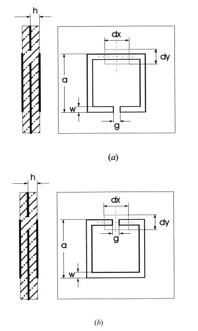
Fig.2: Two microstrip open-loop resonators, (a) Coupled Magnetically, (b) Electrically.
Figure 3 shows the resonator band-pass filter structure consisting of two arrays of micro-strip open-loop resonators on the outer side of the two dielectric substrates with a common ground plane in between.
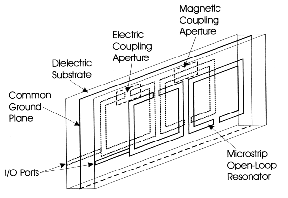
Fig. 3(a): Structure of micro-strip open-loop resonator filter
A comprehensive electromagnetic simulation was conducted to explore the characteristics of two aperture couplings, as detailed by Hong and Lancaster in 1999. The simulation revealed two distinct resonant-mode frequencies, evident from the corresponding peaks. The diameter of the microstrip line played a pivotal role in influencing the separation and strength of the two modes. Larger diameters resulted in wider mode separation and enhanced coupling strength.
Remarkably, the low-frequency mode of electric coupling and the high-frequency mode of magnetic coupling remained constant, irrespective of coupling strength or aperture size. This contrasts the behaviour observed in single-layer microstrip coupled resonators in an open loop, where both mode frequencies fluctuate with varying coupling strength. The variation in this case is attributed to the impact of coupling-aperture resonant frequencies on uncoupled resonators.
The increase in inductance-resonance was observed to be amplified with the orientation of the aperture at the ground plane. Consequently, the resonant frequency of microstrip open-loop resonators is anticipated to decrease concerning a magnetic aperture or increase concerning an electric aperture. Hong and Lancaster's 1999 study substantiates uncoupled resonators' electromagnetic simulated resonant frequencies in the presence of a coupling aperture.


Coupling Coefficient
Microwave band-pass filter design commonly integrates resonator coupling coefficients, allowing for the precise synthesis of narrow-band filters. This accurate technique extends to the optimization synthesis of wideband filters, utilizing initial structure parameters. Notably, intelligent filter optimization techniques often leverage the physical properties of resonator filters, as recognized by Cohn (1957) and Hong and Lancaster (2009).
The asymmetrical slopes of baseband filters result from the frequency dispersion of coupling coefficients. Simultaneously, attenuation poles become null primarily due to the impact of resonator coupling coefficients. The peculiar dependence of coupling coefficients on the distance between certain resonators is elucidated by an energy-based approach to coupling coefficients, as elucidated by Belyaev et al. in 1996. Presently, a standardized definition for a resonator coupling coefficient is unavailable. In the context of wideband filters characterized by strong coupling, the distinctive nature of the resonator coupling coefficient is further revealed.
Resonant Band-Pass Networks
The first person who introduced the coupling coefficients into the microwave filter theory was M.Aisal (Hong and Lancaster, 1999). The researcher started his work from a bandpass network of alternate and/or parallel resonant (dissipative) circuits set to the same resonance frequency.
The coupling coefficient he defined for this network between adjacent resonant circuits is as follows:
, (3)
Where,
Cs = Capacitance of the Resistor Inductor Capacitor (RLC) resonant circuit, and Cp = Capacitance of R.L.C resonant circuit (parallel). The Network Transfer Immitance expression is a ratio of the frequency ω, proportional to the product of coupling coefficients of every bordering resonant-circuits. In contrast, the denominator comprises () with the maximum exponent n, the number of resonant circuits. Each coefficient in the polynomials is an exclusive function of the resonant circuits' coupling coefficients and the Q-factors. The algebraic expression can be given as a Chebyshev polynomial at some values of the coupling coefficients of the circuits. The simultaneous equations for those values have been expressed and derived by Hong and Lancaster in 1999 for the value of n up to or equal to four. So, the coupling coefficient k is defined by Cohn, 1957 for an unlimited value range.
The ladder-chain of RLC parallel resonant circuits, including capacitive and mutual inductive coupling band-pass network, was considered. Physical accomplishment/production of such a network is much more practical. It has also been expressed that the transfer immittance fraction of the supplementary network is not a polynomial(s) of;
( )
The 2 band-pass networks are more or less equivalent to a narrow pass-band filter case, i.e., when ‘|k|’ << ‘1’. Their transfer function coincides in the region of ω0 if |k| = |k (ω)|, where
(4)
(5)
(6)
The C1., L1., C2., L2.= Inductances, Capacitances of 2 parallel coupled resonant circuits, and Cm, Lm= Coupling capacitance and mutual inductances. kL and kC are inductive and capacitive constants for coupling coefficients of 2 parallel resonant circuits.
Thus, the coupling coefficient k(ω) for 2 parallel RLC resonant circuits is the sum/addition of two frequency-dependent expressions. The first expression is said to be related to capacitive coupling, whereas the second expression represents inductive coupling. The mathematical sum in Eq. (4) may disappear at a specific frequency, given as ωp, in which the transfer function (of band-pass network) has an attenuation pole. The phenomenon indicates that inductive coupling and capacitive capacitive coupling remunerate each other. With a resonant frequency of ω0, both expressions' absolute value(s) in the mathematical addition (4) are limited to unity.
In research conducted by Bovbysh and Tyunev (2010), it was reported that the physical realization of narrow-band filters having no attenuation poles at finite frequencies should provide the real values for resonant-frequency (ω0)) resonator-factors (Q), and ki;i+1 which are the coupling-coefficients (b/w resonators). The expression for the coupling coefficient for such a scenario can be given as follows;
(7)
Where ωe and ω0 = Frequency (s) of coupled-oscillations of resonators, ω0 = Resonant-frequency (s), that is, for all coupling-reactances. In other words, the coupling coefficient in a narrow passband case is defined as a modelled resonant-frequency constant. However, this simplified approach may not always prove to be successful.
The approximate expression was given by Cohn (1957) as;
(8)
Matthaei et al. (1964) found the Expression (8) for a bandpass network of coupled non-dissipative microwave resonators. Yet another definition of the coupling coefficient was used therein:
(9)
Where,
i + 1 is an equivalent network of a microwave filter
bi stands for the susceptance slope parameter for the resonator
The trait admittance of the inverter between parallel resonators i is given by
Furthermore, it should be noted that at resonant frequency ω0, all resonators are bound to have 0 susceptance. Equation (10) can be used to determine the slope parameter.
. (10)
The coupled oscillation frequencies ω0 and ωe of 2 similar resonators are mainly responsible for determining the significance of the coupling coefficients at a resonant frequency, as shown by approximate formulas (7) and (8). Therefore, the coupling coefficient of two identical resonators was expressed by Atia and Williams (1972) as:
(11)
For a weak coupling case, formula (7) and formula (11) are expected to match. A sole mutual-inductive coupling capitulates the |k| value, coinciding with (5) and (6) in sole capacitive coupling. For formula (11) to be applicable, i.e., equation (6) must suit the given below summarizing regulation for coupling coefficients (Atia and Williams, 1972).
(12)
Considering the theory of relativity, formula (12) can be seen as very similar to the velocity-addition equation. The approximate formula for a weak coupling case matches the formula (12) (Ruiz et al., 2008).
(13)
Values for k, kL and kC can be either negative or positive, as assumed by Formulas (11) and (12). The coupling-coefficient sign has a meaningful/considerable value compared to another coupling, such as in simulations and modelling.
As for the case of two coupled series and parallel resonant circuits, the frequencies of coupled oscillations ω± are related to the coupling coefficient (3) as follows:
. (14)
Solving (14) gives the coupling coefficient
(15)
This formula agrees with the approximate expression (7). Being equivalent to (3), it may serve as a definition of k.
Using (11) and (15), one can compare two different coupling coefficients, k and ĸ. They are related as
. (16)
One can see that |ĸ| is greater than |k|. It should be noted that this procedure has never been mentioned in the literature before.
In a bandpass network obtained from a lowpass prototype filter using the bandpass frequency transformation
, (17)
Equation (18) allows us to calculate the frequencies of coupled mode oscillations for resonant circuits.
, (18)
where Ω is the frequency of the lowpass prototype filter with normalized parameters gi.
For a bandpass network with alternate series and parallel resonant circuits, using (15) and (18), it is possible to compute the coupling coefficient values.
. (19)
It should be noted that the results obtained from the approximate formula ki,i+1 match with those found from the exact method ĸi,i+1.
Coupling Coefficients and Filter Optimization
Various optimization techniques are used in the software packages for microwave modelling. The smart/intelligent methods for microwave optimization have been proven to be much more useful and effective than ordinary optimization techniques because intelligent techniques use preliminary design information. One such technique was presented by (Belyaev et al. 2006) for band-pass microwave filters. Smart and intelligent optimization techniques aim to produce the required pass-band and not vary the design parameters much. These parameters are kept constant to be used for further optimizations, for example, miniaturization. An objection feature of the intelligence optimization technique is the deflection vector D with n + 1 components.
For n+1 components, n represents the number of resonators in the filter. The first three components are defined as
(20)
(21)
, (22)
where ωc is the current centre frequency, ∆ω0 is the current bandwidth, and Ri is the ith maximum reflected power numbered in the frequency axis direction [5, 6]. Definitions of other components depend on n. In the case of a four-resonator filter,
(23)
, (24)
Understanding how to build a proper conjugate correction operation for each deflection component is possible by following certain rules applicable to the intelligence optimization method.
These rules operate in terms of such physical quantities as resonant frequencies of all resonators, external Q factor of input and output resonators, and coupling coefficients for all pairs of adjacent resonators. Components of the deflection vector D are divided into even and odd relative to the centre frequency or centre reflection maximum(s). The odd components are D1 and D4. Even components are D2, D3, D5.
Each physical quantity is matched with one of the best suitable structure parameters, e.g., the coupling coefficient |k| is matched with spacing S between resonators.
The correction operation for an odd component involves correction operations for frequency-related structure parameters. The correction operation for an even component involves correction operations for coupling-related structural parameters. For example, the correction operation for D5 > 0 comes down to increasing the coupling coefficient |k12| and simultaneously decreasing the coupling coefficient |k23| to assure that the value of the product is not changed, i.e. |k12|2|k23| (Belyaev et al., 1996).
All correction operations associated with deflection vector apparatus/components are quasi-orthogonal, which specifies that every correction operation, with the elimination of conjugate-deflection-component, produces other deflection components having an absolute value lower than the absolute value of the initial deflection component.
Computation and examination of strip and microstrip filters and analysis and synthesis have been successfully performed over the last ten years using intelligence optimisation techniques (Belyaev et al., 2007). The intelligence optimisation method has recently become widely used for bandpass filters with dual-mode resonators. Instead of using one oscillation ode per resonator, the pass band formation in these filters incorporates two vibration modes. It is recommended to treat each dual mode filter resonator as a pair of a couple of single mode resonators for the rules formulated for single mode filter to be applicable. Therefore, the two resonant frequencies of the dual-mode resonator must match the frequencies of coupled vibration in such an imaginary setting. A simulation or experiment can be performed to obtain an answer to how to control the coupling coefficient and resonant frequencies of coupled imaginary resonators.
Another area of application of coupling coefficients for filter optimization is the coupling matrix (Li et al., 2008) and the extended coupling matrix, which are even. Coupling coefficients kij between jth and ith resonators are the off-diagonal elements of these matrices. Cross-coupling between non-adjoining resonators can, therefore, be achieved. It is assumed that the coupling coefficients in these matrices are not dependent on frequency. Furthermore, it is possible to calculate the frequency response of an equivalent network using the extended coupling matrix and the coupling matrix. Space mapping optimisation of coupled resonator microwave filters is also based on these common models (Amari et al., 2006).
A similarity transformation for the extended coupling matrix can be completed as we move to a linear combination from resonator voltages. The overall frequency response is unaffected by these transformations, so it would not be wrong to say that all these transformations are alike. One of these transformed matrices is known as the transversal matrix, which results in all off-diagonal elements being zero. On the other hand, the diagonal elements of the coupling matrix are taken as the Eigenvalues. Additionally, it should be noted that the Eigenmodes are not attached. Amari and Bekheit (2007) thoroughly discuss this concept's similar transformations and physical understanding.
Conclusion
This report details the design process of spiral microstrip filters, specifically focusing on Chebyshev and quasi-elliptic filters. The design considerations encompassed external and internal couplings, elucidated through diagrams, with calculations to determine the optimal structure. The introduction of microstrip patch capacitors between resonators was found to enhance coupling, with a consequential increase in external coupling. Notably, patch capacitors allowed for omitting via holes in the filter structure.
The quasi-quarter-wavelength resonator filters demonstrated a notable advantage by avoiding resonance at twice the main resonance frequency. Moreover, it was observed that maintaining equality in the resonant frequencies of resonators could result in an asymmetric response in a filter with nonadjacent coupling. To address this, non-identical resonators were employed while preserving symmetry, establishing two transmission zeroes on either side of the filter response.
Two spiral filters were designed, simulated, and fabricated—a Chebyshev filter and a quasi-elliptic filter. The measured results are closely aligned with the simulated outcomes. The fabricated Chebyshev filter exhibited a 20% bandwidth, while the quasi-elliptic filter had a 12% bandwidth around 1 GHz. This underscores the efficacy of the quasi-quarter-wavelength spiral resonators method in practical microwave filter applications, yielding highly satisfactory results.
Get 3+ Free Dissertation Topics within 24 hours?
References
Amari, S., LeDrew, C. and Menzel, W., 2006. Space-mapping optimization of coupled-resonator microwave filters. IEEE Transactions on Microwave Theory and Techniques, Vol. 54, No. 5, 2153-2159.
Amari, S. and Bekheit, M., 2007. Physical interpretation and implications of similarity transformations in coupled resonator filter design. IEEE Transactions on Microwave Theory and Techniques, Vol. 55, No. 6, 1139-1153.
Atia, A. E. and Williams, A. E., 1972. Narrow-band waveguide filters," IEEE Transactions on Microwave Theory and Techniques, Vol. 20, No. 4, 258-265.
Awai, I., 2006. Meaning of resonator’s coupling coefficient in band-pass filter design. Electron Communication, Japan, Part 2, pp.1–7.
Belyaev, B. A., Kazakov, A. V., Nikitina, M. I. and Tyurnev, V. V., 1996. Physical Aspects of Optimal Tuning of Microstrip Filters, Kirensky Institute of Physics.
Belyaev, B. A. and Tyurnev, V. V., 2006. The method for microstrip filters parametric synthesis, Microwave &Telecommunication Technology, pp.17-19.
Belyaev, B. A. and Tyurnev, V. V., 1992. Frequency-dependent coupling coefficients of microstrip resonators. Elektronnayatekhnika. Ser. SVCh-Tekhnika, No. 4, 24.
Cameron, R., 2003. Advanced coupling matrix synthesis techniques for microwave filters. IEEE Transactions on Microwave Theory and Techniques, Vol. 51, No. 1, 1-10.
Cohn, S.B., 1957. Direct-coupled-resonator filter. IRE, Vol. 45, pp.187-196
Dovbysh, I. A. and Tyurnev, V. V., 2010. Synthesis and investigation of three-section microstrip filter on folded dual-mode stepped-impedance resonators," Progress In Electromagnetics Research M, Vol. 12, pp.17-28
Dovbysh, I. A. and Tyurnev, V. V., 2009. Peculiarities of intelligence optimization of a microstrip filter on folded dual-mode resonators, PIERS 2009 in Moscow Proceedings,
Gashinova, M. S., Goubina, M. N., Zhang, G., Kolmakov Y. A., Kolmakov, I. A. and Vendik, I. B., 2003. High-Tc superconducting planar filter with Chebyshev characteristic. IEEE Trans, Theory Technol, pp.792–795.
Hong, J. S. and Lancaster, M. J., 1996. Couplings of microstrip square open-loop resonators for cross-coupled planar microwave filters. IEEE Trans. Microw. Theory Technol, pp.34-77
Hong, J.S. and Lancaster, M. J., 2001. Microstrip filters for RF/microwave applications, chap. 3. New York: John Wiley & Sons, Inc.
Hong, J.S. and Lancaster, M. J., 2001. Microstrip Filters for RF/Microwave Applications, John Wiley & Sons, New York.
Hong, J.S. and Lancaster, M. J., 1999. Aperture-coupled microstrip open-loop resonators and their applications to the design of novel microstrip bandpass filters, IEEE Trans., MTT-47, Sept.
Huang, F., 2003. Ultra-compact superconducting narrow-band filters using single- and twin-spiral resonators. IEEE Trans. Microw. Theory Technol, pp.487–491.
Huang, F. and Xiong, X., 2003. Very compact spiral resonator implementation of narrow-band superconducting quasi-elliptic filters. InProc. 33rd Eur. Microw, Germany, pp. 1059–1062.
Matthaei, G. L., Young, L. and Jones, E. M. T., 1964. Microwave Filters, Impedance-matching Networks, and Coupling Structures, McGraw-Hill, New York.
Ruiz, J. A., Wang, C. and Zaki, K. A., 2008. Advances in microwave filter design techniques, Microwave J., Vol. 51, pp.26-42
Li, G., Dai, X. W. and Liang C. H., 2008. Fast synthesis of coupled-resonator filters. Journal of Electromagnetic Waves and Applications, Vol. 22, pp.5-6,