
How does the Composition of Cement Affect the Design of Civil Engineering Structures?
February 27, 2021
Application of Lean Tools & Techniques in Cigarettes Production – A Literature Review
February 27, 2021Introduction
An experimental study was completed to develop understanding of discharge over a broad crested weir. Before looking into the experimental procedures, it is important to understand the fundamental principles applied to the broad crested weirs, for which detailed research has been completed by British Standard BS3680 Part 4F:1990. The extracts of these standards were reviewed along with other related literature, and theoretical models proposed in these standards have been used to complete this experimental research.
The broad crested weirs are mostly used to measure the flow of rivers, as they are more suited as compared to other relatively sharps crested weirs. They are generally constructed using reinforced concrete to ensure robust characteristics of its structure.
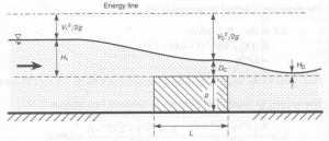
Figure 1: Discharge over a brad crested weir (source: JF civil engineer)
However for the purpose of this study, the broad crested weir is used as an open channel flow analyses device which integrates the hydraulic characteristics of a weir in a flume.
Aim of Research
The aim of this research is to compare experimental and theoretical discharge over a broad crested weir. The flow characteristics over a weir will be analyzed and the parameters that affect the flow profile will be determined.
The experimental study is aimed to review the energy and continuity equations associated with broad crested weir discharge and understand the fundamental principles behind this engineering process.
Apparatus
The apparatus used in this experiment primarily included a fume and a weir structure, as shown in the Figure 1 below;
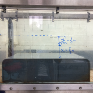
Figure 2: the Flume and Weir structure
The other equipment used in this experiment included;
- Water Pump and a flow valve; to provide flow of water over the crested weir
- Ultrasonic Flow Meter; to record the discharge flow rates over the weir
- Measuring tape; To record and adjust the upstream gauge heads
Note: The readings were taken for 2 different input values; however the same apparatus was used for both the experiments.
Experimental Procedure
A simple approach to the experimental procedure was followed, which has been outlined in this section. Before starting the fluid flow, the geometry of the weir structure was recorded to obtain the following dimensions;
- Length (L); 597 mm
- Height (p); 165 mm
- Weir width (b); 300 mm

Figure 3: process flow diagram for discharge over broad crested weir
The procedure methodology adopted in the experiment was as follows;
A scale diagram of the structure was developed, as shown in the figure 4 below
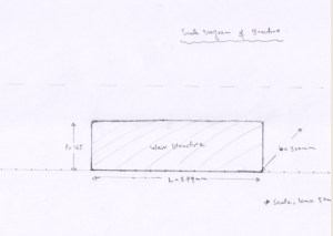
Figure 4: Scale diagram of weir structure (scale; 1:5, Units: mm)
The water pump was switched on and flow valve was adjusted to provide an upstream head (h) of gauge pressure 90mm. The head was recorded.
In the next step, the discharge flow over the structure weir was recorded using the ultra sonic flow meter. The measured flow was recorded as; Qe = 11.60 lit/s
The flow profile of the stream over the weir was the recorded for every 50 mm increment of lengths, the values obtained were recorded on the scale diagram, as shown in the figure 3 below;
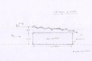
Figure 5: Flow profile of the stream over the weir for 90 mm head (scale; 1:5, Units: mm)
The recordings taken were saved for this experiment, and the upstream head (h) of gauge pressure set value was re-adjusted at 148mm (this will be referred as experiment 2 in the next chapter). The discharge flow for this increased head was recorded as Qe = 30.60 lit/s, and the flow profiles recorded is as follows;
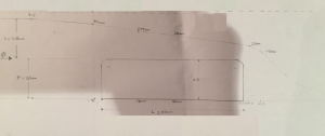
Figure 6: Flow profile of the stream over the weir for 148mm head (scale; 1:5, Units: mm)
Data and Results
The results obtained from the experimental procedures for the flow profile is given in the table 1 below;
Table 1; Results of Flow profile (with h= 90 mm)
| Weir Length | Flow Profile (total head in mm) |
| 0 | 255 |
| 50 | 253 |
| 100 | 244 |
| 150 | 233 |
| 200 | 230 |
| 250 | 226 |
| 300 | 225 |
| 350 | 225 |
| 400 | 225 |
| 450 | 224 |
| 500 | 215 |
| 550 | 202 |
| 600 | 186 |
The resulted trend line is represented as follows;
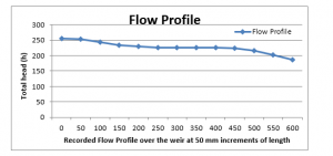
Figure 7: Flow profile of the stream over the weir for 90mm head
The same results are also plotted in terms of the actual gauge head over the weir, via subtracting weir height (p) of 165 mm from the total head, producing the following graph;
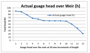
Figure 8: Actual gauge head of stream over the weir for 90 mm head
And for the Experiment 2, in which the head was raised to 148 mm, the following data was recorded;
Table 1; Results of Flow profile (with h= 148 mm)
| Weir Length | Flow Profile |
| -50 | 313 |
| -30 | 304 |
| 150 | 279 |
| 300 | 264 |
| 595 | 221 |
| 645 | 195 |
Producing the following flow profiles;
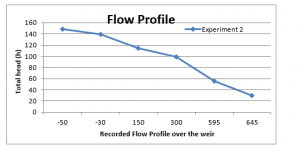
Figure 9: Flow profile of the stream over the weir for 148 mm head
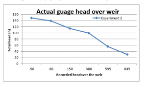
Figure 10: Actual gauge head of the stream over the weir for 148 mm head
Calculations
Computations were performed for both the set gauge head values; Experiment 1 with h adjusted to 90 mm, and Experiment 2 in which h was raised to 148 mm.
Experiment 1;
- The Discharge Coefficient Cd is calculated through the BS equation 6a (British Standard BS3680 Part 4F:1990)
Where b is the weir width, which is 579 mm and h is the upstream gauge head, which was adjusted as 90 mm. Replacing these values gives us;
- The Velocity Coefficient (CV) can also be determined using the BS chart of coefficient of approach velocity. It is important to note at this point that for a full width weir (b= B), the axis term becomes Cd h / (h + p).
Therefore, from the BS chart,
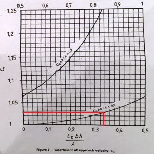
Figure 11: Velocity Coefficient –CV (source BS extracts)
CV
- The theoretical discharge, QBS is also calculated using the BS equation;
- In order to compare the measured and the theoretical BS values of discharge, the percentage error has been determined as;
Error = ((QBS – Qe) / Qe) x100 %
= 13.6 – 11.6 / 11.6 x 100 %
= 17.24 %
- The critical depth has been calculated using the relation;
yc = (q2 / g)1/3
Where q is the unit discharge = Qe / b, and for this experiment, this is = 0.0136 / 0.3 = 0.04533
Then,
yc = (0.045332 / 9.81)1/3 = 0.05939 = 59.4 mm
- In Oder verify the value Cv calculated in ii), the following BS equations have been used to determine the theatrical value of Cv for this experiment;
And,
Where v is the velocity at the gauging position and a has been taken as 1. This gives;
Now, v can be calculated, as we know the actual flow rate i.e. 11.6 lit/s. Since V =Q/A, and at the gauging position, the channel depth is 255 mm and the channel width which is the same as the weir (b) is 300 mm, then;
v = 0.0116 / (0.255 x 0.30)
v = 0.151634 m/s
Thus giving;
And;
This value is very close to previously calculated value of 1.029 as the coefficient simply based upon geometry.
Experiment 2;
The same calculations were repeated in this experiment, but with the increased upstream head (h) of gauge pressure of 148 mm
- The Discharge Coefficient Cd is calculated through the BS equation 6a (British Standard BS3680 Part 4F:1990)
Where b is the weir width, which is 579 mm and h is the upstream gauge head, which was re-adjusted as 148 mm. Replacing these values gives us;
- The Velocity Coefficient (CV) is also determined using the BS chart of coefficient of approach velocity;
And from the BS chart,
CV
- Similarly, the theoretical discharge, QBS, is also calculated as;
- The comparison of measured and theoretical BS values of discharge, in-terms of % error has been determined as;
Error = ((QBS – Qe) / Qe) x100 %
= 29.66 – 30.6 / 30.6 x 100 %
= 3.07 %
The critical depth has been calculated using the relation;
yc = (q2 / g)1/3
Where q = Qe / b, and for this experiment, this is = 0.0306 / 0.3 = 0.102
Therefore,
yc = (0.010404 / 9.81)1/3 = 0.1019 = 101.9 mm
The value Cv is determined as;
= 0.1534
Where v = 0.0306 / (0.313 x 0.30), and,
Here again, the value is very close to previously calculated value of 1.049 as the coefficient simply based upon geometry.
Now, or this larger discharge, method detailed BS Annex C is also used to determine the value of Cd. This will provide comparison with the value determined earlier. According to the BS Annex C;
Assuming that S*/L = 0.003, and for smooth plastic, roughness (k) = 0.003 mm. At the recorded water temperature of 20 deg C, the kinematic viscosity is 1.01 x 10⁻⁶, and v = 2/3 g h ½ giving;
Note: from the BS Annex C calculations method, v = (2/3 g h) ½ = 0.968 m/s, L/k = 50,000, and Re = vL/v = 5.72 x 10⁵
This is also very close to the previously calculated Cd value of 0.971. This is because both the methods have very similar assumptions, thus the final equations are almost similar to each other. However, this method is considered as more accurate for calculating the discharge coefficient as this is based upon the displacement thickness concept.
Measurement of Drowned Flow
The discharge over a weir is a function of upstream depth, and the flow is considered to be modular when it is independent of the variations in tail water level. In-case the tail water depth increases, at a certain point it start to influence the discharge condition over the weir. This is the point where the flow is considered as drowned flow. This point is referred as the critical depth (Hd) of flow profile.
Therefore in order to ensure that the BS equation is applied to the profile and flow remains modular; the critical depth must not disappear from the weir crest. If Hd does exceed the critical depth, the backwater from downstream causes the weir to submerge. This can be expressed as submergence ratio H2/H1.
Therefore, in order to maintain the modular flow, the modular limit will have to be maintained. This can be accomplished through raising the height if weir crests (p), however it has to be optimized such that possibly of upstream flooding is avoided.
Much research has been conducted in the last many years and the submergence ratios have been proposes by BS, at which the flow profile changes from modular to drowned flow. The summary of which is given as below;

Figure 12: Submergence Ratio (source BS extracts)
For the purpose of this study, the downstream depth (hd) was gradually increased to the point at which the downstream conditions started to affect the upstream conditions. The Hd at this point was determined and the results were as follows;
HD = 92 mm
This was achieved at upstream total head (H1) of 118 mm, giving;
H1 / p = 0.715
Now, the modular limit / submergence ratio therefore is;
H2 / H1 = 78%
Comparing the results with the Figure-12 above shows that: the obtained limit is quite close to the values suggested by BS, strengthening the fact that the BS standards propose a good method of design estimation for discharge over a broad crested weir.
6. Discussion
The flow profile in the Experiment 1, where the gauge head was set at 90 mm, showed that discharge over the weir is not very steep, the flow/discharge starts to settle at the critical depth (yc) of 225 mm (59.4 + 165 mm). This is because of lower flow rate and a lower upstream gauge head (h).
However, as the gauge head was increased to 148 in the experiment 2, the flow rate increased and the discharge head’s gradient also increased. This produced a continuously decreasing trend line in terms of the stream depth. The critical depth (yc) was observed to be considerably low (at 101mm) in this experiment; revealing the fact that an increase on the upstream head will result in the reduction of critical depth.
Another considerable change observed in this experiment was that both the values of CD and CV increased with the increase in the flow rate and upstream head. This relates to the fact an increase in the upstream head will have a considerable impact in almost all the parameters of broad crested weir discharge.
Conclusion
The experiment completed in this research undertook investigation of discharge over a broad crested weir using a weir in a flume. The results were recorded and the BS Equations for a broad-crested were then used to obtain the theoretical values of the same parameters.
The BS theory of weir is basically derived from energy and continuity equations, which have been modified as a result of a large number of experiments to account for energy losses, in terms of boundary layer effects. The experiments completed confirmed that equations are well applied to the weir in our experimental fume, as the comparison between the actual values and of those determined through BS equation were very close.
However, the design parameters also play an important role when comparing the theory with the actual results; as evident from the comparative results of discharge values of measured and BS theatrical values. The % error decreased from 17.24% to 3.07 % for a higher set value of upstream gauge head.
This provided conclusive evidence that although the equations have been modified after excessive experimentations and research work, they can only be applied when optimum flow conditions are maintained. When we go close to the limitations of these equations, the broad crested weir will cease to operate in accordance with the model assumptions. Therefore the weir has to be designed with optimum parameters in order for it to successfully be applied to BS methodology
References
- Azimi, A.H and Rajaratnam, N., (2009). Discharge characteristics of weirs of finite crest length. Journal of Hydraulic Engineering, 135(12):120-125
- British Standard, (1990). BS3680 Part 4F: ISO4374.
- Chin, D.A., (2006). Water Resources Engineering, 2nd edition, Prentice Hall, 2006.
- JF Civil Engineer, (2011). The broad crested weir. Available online at: <http://www.jfccivilengineer.com/index.htm>. [Retrieved 12 November 2014]
- Mays, L., (1999). Hydraulic Design Handbook, McGraw Hill. New York.
Get 3+ Free Dissertation Topics within 24 hours?


