
Civil Engineering undergraduate (2000 words)
February 16, 2021
Proposal
February 16, 2021Chapter 1: Introduction
Designing, Construction and Operation of any building requires expert engineering skills. This project details brief discussions on the Design and Construction of a multi-story residential block. It has been proposed to construct the residential tower of 76 meters height, containing 127 apartments and penthouses. The building is to have 20 stories in total, and a basement car park for the residents of the complex.
The selected location of the project is Ealing Town Centre. The locality conditions and the business environment are best suited for the multi apartment building due to the increasing demand of residential flats. The town is located at the center of various prime locations. The proposed site of the project is located at the north of the Uxbridge Road (A4020), having a 34 meters long front on this road. The rear side of the site borders with the residential property in Craven Avenue. The site has a depth of 105 meters, giving the total area of the site as 3346 m2. The figure below shows the site location in detail.
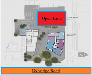
Figure 1: Site Location (edited, lecture notes, 2013)
As it can be observed through the figure above, the site has an empty space which was created by demolition of a multistory building. The site has built-up areas in the surroundings, including apartment blocks, which make the site commercially viable. The geology of the site comprises of chalk, Thanet Sands and River Terrace Gravels and the backfill materials.
Chapter 2: Layout
Preparation of the site layout and the conceptual design is the first step of any construction project. The concept of the project is to provide state of the art residential facility in the subject area. Constructing a building is not the only concern of the developers, as the design team has to consider various other aspects of the project such as providing facilities for the wellbeing of the building occupants.
Therefore, it has been proposed to build fee and open green spaces and car parking facilities at the site. Facilities such as car parking (s), playing areas, and open sitting spaces are considered to be an essential part of the concept as these would allow an excellent environment for the residents. The building would also accommodate heath facilities, gym, swimming pool and sitting lounges. The figure 2 below presents the site play out, showing only the building foot prints.
The entrance of the site has been proposed to be boulevard frontage, from the Uxbridge Road. The underground car park and the Open visiting car park, both are provided such as to provide easy access from the site entrance. The swimming pools, playing area and the sitting areas are provided close together so that the families could use all these facilities without having to walk long ways. The main store, waste collection, supplies and the control/plant room has been provided at the back of the Tower structure, as public access is not required in these areas. An emergency exit has also been provided at the back of the tower in order to meet the safety and security standards
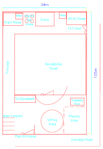
Figure 2: Site Layout Plan
Since it is a mega project, much engineering works will have to be completed to ensure the successful operation of the project. Any lack of the engineering works could adversely affect the project. It must be noted that any work which is completed after the completion of the project can cost heavily. Therefore, much consideration is given to the following engineering works;
- Site Plan in accordance with the required facilities (such as HVAC, Water Reservoir, Power Supply / Plant Room etc)
- Building structure to be completed with high quality materials and in accordance with the approved plan
- The Electrical works in accordance with the required or expected load.
- The piping works to completed for all parts of the tower and the site (including for water and gas pipelines)
- Air Supply design and infrastructure, and ventilation system for all parts of the tower
- Safety and Security System
Chapter 3: Waste Management
The site waste management plan (SWMPs) is one of the most important management activities which must be finalized/approved before the construction process is initiated. The waste management plan is comprised of the following;
- Waste Generation
- Waste Collection and storage
- Treatment and use of the waste in accordance with the procedures approved
- Disposal or transfer of waste
The SWMPs have been considered to be quite productive for the overall project management. The plan aims to promote the waste minimization and maximum utilization of the materials to be used on the site. The SWMP of the site of this project will provide the following benefits;
- Highlight the areas where the waste is generated and identification of the types of waste expected to be generated on site
- Characterization of the waste in accordance with the treatment/disposal methods
- Outline the methods of collection and designate the location of the waste placement in accordance with the characterization
- Waste treatment/use and disposal methods
Therefore, the correct implementation of the waste management procedure would have an influential impact on the project; the management of the project would improve, the jobs/activities will be completed on time, the performance of the material utilization would enhance, less waste will be produced, and most importantly, the waste generated will be reused and/or recycled where possible. Further to this, the waste disposal procedure would ensure that hazardous/toxic waste is not discharged to environment.
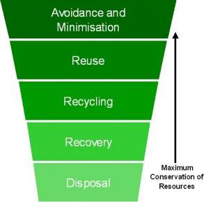
Figure 3: Waste Management (Source: Recipro2011)
Since the SWMPs have been reported to be very beneficial, environmental protection agencies have implemented the SWMPs legislation in the United Kingdom, according which it is now required by law to implement the waste management procedures for any project worth more than three thousand pounds. The waste types and the expected quantities are also tabulated, which highlights the expected type of waste generation on site.
On-site waste is expected to be generated through activities such as excavation, demolition and construction. The waste will also be brought into the site in form of packing and materials. The waste is characterized as Inert, biodegradable, non-biodegradable, hazardous, toxic, flammable etc. The accumulated waste types are then proposed to be processed such that these are best utilized and have a positive environmental impact. The following table provides the expected waste types and the respective quantities;
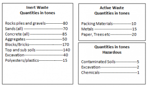
Total waste expected to be accumulated/generated would therefore be 703 tones
Chapter 4: Environmental constraints and Mitigation measures
Waste minimization efforts and optimized utilization of waste is the key driving factor of the waste management practice on site. The practice also ensures that the recyclable and reusable materials are separated and processed accordingly. The recycling and reuse of materials is beneficial in many ways as it maintains the balance of environmental integrity and the carbon emissions/footprints are minimized.
The waste types such as concrete, tarmac, bricks, blocks/piles etc. will be reused on site where possible. If not required, the materials will be sent/sold to vendors in the form of re-usable materials. Materials such as metals and plasterboards will be sent for recycling off-site. All the construction materials which will not be used or saved through the re-use policy of materials will be sent to other projects. Some of the materials might as well be saved in the store for future use (such as tiles/paints etc)
Although the waste management is expected be beneficial for the environment, the mitigations measure must be also be considered in order to reduce the environmental impact due to the construction process. Apart from the hazardous waste, pollution in the form of noise and mal-practices such as washing of chemical etc. could discharge harmful materials to the environment.
The natural habitat must be protected, and therefore there is a need implement the mitigation measures for the project. Mitigation Measures Method Statement will be generated which would highlight all the key measures and practices to be taken to avoid the adverse effect on the local habitat.
The release of air pollutants will be controlled through implementing the transportation rules on the site. Quantity of vehicle on site, speed of vehicles, any processes which may need reaction/burning of materials, and use of heavy equipment(s) will be controlled in accordance with the regulation of the local council and site forman. Contaminated materials release to the environment/surrounding lands will be controlled through documented chemical and water usage on site. All the preparation of engineered fluid, washing, and other sources of discharge of fluids will be controlled through onsite mitigation measures/procedures. It will be further ensured that all the relevant personnel on site are introduced to the ecological constraints
Chapter 5: Construction Schedule
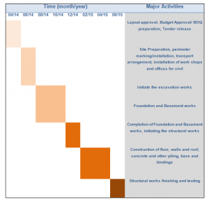
Project construction schedule is one of the primary requirements of the project construction planning. The Construction schedule has been introduced for this project to ensure that the all the activities involved in the construction process are outlined with respect to the time of activity/process initiation and completion. The construction schedule further provides the approximate completion time of the project.
The figure below presents the construction schedule of the residential tower. Staring form the development of the concept, all the main activities are included in the schedule, till the structure of the tower is completed
Table-1: Project Schedule
Chapter 6: Construction Schedule
For the construction of the new road, earth work calculation have been performed to analyze the key parameters involved, and aid in the design, construction and planning of the construction process. Along the tower frontage, a Road of 100 meters has been planned to be constructed, for which the shrinkage factor (compaction of soil at the final destination) has been calculated to be 0.8. The shrinkage factor has only been considered in the calculation where the volume is positive, otherwise the factor is considered as 1. The Table below gives the calculated values of the cumulative volume;
Table 2: Earthworks Calculations
|
Chainage (m) |
Volume (m3) |
Cut (+ive) |
Fill (-ive) |
Shrinkage factor |
Equivalent volume |
Cumulative volume |
|
0-10 |
20 |
+20 |
- |
0.8 |
16.00 |
16.0 |
|
10-20 |
48 |
+48 |
- |
0.8 |
38.40 |
54.4 |
|
20-30 |
20 |
+20 |
- |
0.8 |
16.00 |
70.4 |
|
30-40 |
-30 |
- |
-30 |
1.0 |
-24.00 |
40.4 |
|
40-50 |
-38 |
- |
-38 |
1.0 |
-30.40 |
2.4 |
|
50-60 |
-32 |
- |
-32 |
1.0 |
-25.60 |
-29.6 |
|
60-70 |
-28 |
- |
-28 |
1.0 |
-22.40 |
-57.6 |
|
70-80 |
-12 |
- |
-12 |
1.0 |
-9.60 |
-69.6 |
|
80-90 |
-5 |
- |
-5 |
1.0 |
-4.00 |
-74.6 |
|
90-100 |
15 |
+15 |
- |
0.8 |
12.00 |
-62.6 |
|
|
|
|
|
|
|
|
Plotting the cumulative volume against the chainage gives the Mass Haul Diagram;
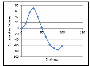
Figure 4: Mass Haul Diagram
The Mass Haul Diagram has been widely used to provide support in completion of the earthworks, planning, design, and construction stages of the project (Lecture Notes, 2013)
Chapter 6: Investigations and Justification- Construction Techniques
The construction work of the residential tower begins with the site preparation and initiating the foundation works. The basements and exaction works are completed along the way and the building frame works are completed, before the floor slabs are constructed. The details of the engineering works of all these activities are not provided as these are out of scope of the report, however the brief details on the foundation, basement and structural frame has been included in this section.
Foundation:
Construction of deep foundations has been proposed for the tower construction as the subject building is very tall and it has been designed to accommodate 127 apartments over 20 stories. The deep foundations have been recommended because these foundations are able to provide the load carrying support to the structure of the building. The vertical/lateral and/or uplift forces are resisted and foundation load is transmitted to the solid ground.
The bored piles of large diameters are to be utilized for the project since these types of piles are considered to be most suitable for the tall multi storey buildings. The foundations are constructed from concrete in pile caps and pad foundation forms below the surface of the ground. The bottom of the steel columns will have a steel base plated which is constructed to transform the column forces to the foundation. The engineered fluid made up of concrete is filled in the pile shaft which goes into the solid/hard soil.
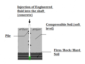
Figure 5: Foundation works (source: edited, lecture notes 2013)
Basement
The underground car park is to be provided for the residents of the tower. The cark park is to be constructed in the basement of the hotel structure. The grade 3 basement, which is classified as having dry environment, and best suited for residential and commercial services is proposed to be constructed. The basement support will be provided by the diaphragm walls. These walls are known to provide cost effective and rigid permanent retaining walls. These also offer less construction joints and are suitable for large sites. The walls are constructed through the reinforced concrete using the under slurry technique.
The method of construction to be used for the tower basement is the top down construction method. The methods will be used for tall buildings and underground structures such as car parks. The basement floors are constructed as the excavation process is progressed. The procedure followed for the construction is as follows;
- Retaining wall is constructed
- Piles are constructed and steel columns are placed
- Excavation process is initiated
- Floor slabs are casted for the first basement level
- The super structure is constructed
- The steps of excavation, casting of floors are repeated for the second level, until the desired depth is attained
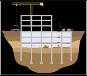
Figure 6: Basement works (source: Case foundation, 2013)
Structural Frames
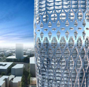
Steel Frame has been proposed to be used for the construction of the 20 storey residential tower. The is because the steel frame have been reported to be more cost effective as compared to other structure types, and are more environmentally friendly due the ability of recycling and re-usage. The steel frames further provide the benefit of immediate strength, durability and adaptability.
The structure also can provide accurate dimensions and are easy to install on the site, and are fabricated off site, which saves a lot time and hence cost of the project. The steel frames further can be installed at wider angles, which can provide sufficiently spaced wide flats. In order to avoid rusting of steel, the frames are protected through the powder coating, which is thermally reacted as layer on the steel. The precast concrete slabs are used for floors of building. The partitions of the walls with the flats could be made of thermal sheets which can save cost and offer design adoptability.
Steel Structure (source: flavahome, 2013)
Chapter 7: Evaluation and Reflection
The construction of the multi storey residential tower requires various engineering tasks to be performed, and implementation of quality management techniques have to be adopted. From the initial concept to the final construction of the building structure, the construction techniques were analyzed and brief summary of details were presented. Critical analyses of the waste management practiced and materials to be used were also completed
It was learnt from the research completed that the every aspect of the design, construction and management is absolutely critical for the successful completion of the project. Intensive research and planning skills were leant from the study completed. Earthwork calculation and project scheduling skills were also learnt through completing the required design and planning works of the project
References
Anderson, M. and Carter, C. J. 2009. “Are You Properly Specifying Materials?,” Modern Steel Construction, January 2009
Architectural Design, 2013. Dorobanti Tower, Romania by Zaha Hadid . Available online at: http://flavahome.com [Retrieved on 06 December 2013].
Beall, Christine, Masonry, 1997. Design and Detailing for Architects, Engineers, and
Contractors, Fourth Edition.
Building Sustainable Communities, 2013. Available online at: http://blog.recipro-uk.com [Retrieved on 06 December 2013]
Cochran, M. and Honeck, W. C. 2004. Design of Special Concentric Braced Frames. Structural Steel Educational Council, Moraga, CA.
International standardization organization, 2006. Environmental Management, Life cycle assessment, Principles and framework.
Lecture Notes, 2013. Semester 1, Civil Engineering Construction, University of West London pp.1-84
Top Down Construction, 2013. Services | Case Foundation Company. Available online at: www.casefoundation.com [Retrieved on 06 December 2013]


