Efficient Construction Analyses- Case of BIM
February 27, 2021
Decision Support Systems; an Overview
February 27, 2021Chapter – 1; Introduction
Much research has been completed in the field of fire engineering in the last many decades. Results have been published with respect to the development of fire, and various simulation models have also been presented to highlight the expectancy of fire development under various conditions (Purser et al., 2010; Karlsson, and Quintiere 2000; Janssens, 2002; Hayasaka, and Kudou, 1997).
The advancement of a fire in a room is mostly influenced by the amount of flammable material and its placement in the fire containment. The supply of oxygen is another vital component. Assuming that the compartment where the fire begins is a closed space, its power will diminish gradually, which implies that there will be a drop in the temperature of the smoke gasses in the closed room. In a few cases, it might happen that a window may break, for instance, and the new oxygen supply will give the fire new impulse. Parameters such as rate of mass loss of fuel and rate of heat discharge are significant in any type of fire (Enclosure fires, 2001).
As demonstrated in following figure, we typically utilize a fire growth graph to depict the development of a fire. The importance of this figure is crucial and will be utilized as a reference in this experimental research. The horizontal axis represents time and the vertical axis represents the smoke gases temperature which accumulates under the confinement. The figure shows conceivable paths for the fire's advancement. The period between ignition and flashover is alluded to as the early phase of the development of the fire.
Throughout the stage of early fire development (Figure 1), the temperature can be seen to progressively rise if there is an opening, for example, a door or a window, within the compartment where the fire is seen to restart. It could be an ordinarily furnished apartment. The fire may advance to flashover, which implies that any ignitable surfaces in the region will radiate products of pyrolysis.
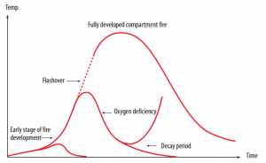
Figure 1: Fire Development Behavior (source: Enclosure Fires, 2001)
In case a flashover occurs, the high amount of heat discharged by the fire rises drastically and if that happens, the fire can be extremely challenging to put out. It is not always the case that a fire advances to flashover. In fact, as various Rescue Services Agencies, this happens in just a small percentage of cases (Backvik, et al., 1996).
After a flashover has occurred, it is principally the oxygen supply access which controls the rate of heat discharge. This stage is a completely developed compartment fire. The behavior of the fire in this stage is critical as far as the numerical figures for the building parts' partitioning and bearing abilities are concerned.
The point when the material in the compartment has been on fire for a long while, the loss rate of mass and fuel and thus, the discharge rate of heat diminishes. Assuming that there are just leakages in a compartment, which is generally shut, it can be seen that the fire does not advance to a flashover because of the absence of oxygen. The intensity of the fire lessens before there is a flashover.
In this case, there are principally two common situations. The fire goes out spontaneously because of an absence of oxygen in the first situation (Andrews, 2007). In the other situation, air is openly available and the fuel amount controls the fire. The reason behind fuel control may be because of the small size of the total fire load, which implies that sufficient heat was not discharged by the fire to cause a flashover. Likewise, it might be because of the way the combustible objects are in an arrangement where the fire can't spread from the initial item. Keeping in mind the end goal to have the ability to figure out how far a fire will spread, it is vital to have a good learning about the fire spread and development.
By now, a mixture of situations which could emerge in the fire room have been depicted. This ought to be clear that it does not imply that these are the only situations which can happen in real life. The actual facts are significantly more complex and the method behind how a particular sort of fire behavior develops is driven by a number of diverse elements (Andrews, 2007). We have officially specified a couple of them, for example, the measure of fuel, the arrangement of fuel and the access to air. Other critical reasons could be the properties materials enclosing the fire (e.g. dividers, glass), particularly heat conductivity.
To have the ability to comprehend a compartment fire, one must have good learning of the chemical and physical procedures which control the development of a fire. Highlighting the importance the concept of fire developments and understanding the chemistry behind it hold pivotal importance, therefore experimentation of fire development with the utilization of varying supply of air/wind has been conducted. A fire growth curve is established, in which the horizontal axis will represent the time of fire (in minutes) and vertical axis presents the temperature of fire. Further details of the experimentations are presented under the methodology chapter and results and discussion chapter.
Research aim
The primary aims of the research are as follows;
- Understanding of the development of fire in different conditions such as wind ambience
- Finding the key parameters that affect the fire establishment through its reaction cycle.
- Establish relationship between fire and the supply of air
Research Objectives and Objectives
The main objectives of the report are follows;
- Conduct experimentations through the use of appropriate equipment; to indentify the relationship of fire development with the key parameters involved; such as rate of reaction/burning, time, temperature and the air supply rates
- Conclude the finding of the experimentations and the associated literature review
- Explore the chemistry of behaviour of fire
- Research and understand the experimental procedures to be undertaken to analyse fire
- Critically analyse the data obtained through experimentations and produce arguments to support understanding of the subject
- Suggest other methods which could have been adopted to attain better results.
- Recommend further research under the same subject based on the results obtained
Chapter – 2; Literature review
The fundamentals of fire
The beginning stage is the point at which fire is caught or initiated by a source. An important element in the development of the fire is whether the source/item or its surroundings have enough fuel for it to develop. In the case where the fire does not spread, it remains controlled by the amount of fuel and eventually burns itself out. The heat released by a ‘fuel controlled fire’ depends on the access to fuel. If this happens, it means there is enough oxygen to combust all the fuel. In the other case, when ventilation is controlling the fire, it is the measure of oxygen and in a way, the size of the opening, which determines the heat discharge. Another crucial factor is the fuel arrangement.
What is the reason for the growth of fire then? The point when the fire can spread, the heat discharge rate will build. The heat released from the starting fire will then cause different surrounding objects to catch fire. The material's fire spread is additionally exceptionally essential regarding how the fire spreads further. The heat discharge rate from one object on fire is usually insufficient to cause a flashover.
Theoretically, there are two ways the fire can expand once it has begun. Either the fire develops or it subsides. Ignition is a chemical process which includes an entire arrangement of chemical processes when fuel is oxidizing. Oxidizing agents react with the fuel. This results in heat and light being released. Therefore, the physical impacts come along the chemical change. Heat is a form of physical energy being discharged throughout the chemical change. A consequence of the fact that there is stored energy in soot particles is that light energy is given out. Ignition is the first noticeable indication of burning. The burnable material can be ignited with the help of an external source, for example, a spark or a match, or it may auto-ignite as a result of the high temperature. When solid materials are being considered, a critical temperature is usually the point at which it ignites. However, this for the most part fluctuates as determined by the material type which is being burnt and can therefore not be utilized as a means of measuring inflammability. The temperature of the surface must be raised up to 300–400°C for ignition to happen with a pilot fire in case of solids. Assuming that there is no flame adjacent, the surface temperature needs to be higher. Wood needs to achieve a 500–600°C surface temperature preceding auto-ignite (PD 7974, 2002).
The process of combustion can in fact be branched into smouldering and flaming combustion.
– Smouldering is heterogeneous oxidation which takes place on the surface when the oxidizing agent and the fuel have different states, e.g. solid fuel and gaseous oxidizing agent.
– Flaming combustion is homogeneous oxidation which takes place when the oxidizing agent and the fuel have different states, e.g. both the fuel and oxidizing agent are gaseous.
Fire spread can likewise be seen as an arrangement of continuous events of ignition. As ignition enormously relies on upon the material's thermal inertia. Quick spread of fire can help the area of the fire to increase, and subsequently, to a rise in the heat discharge rate as well. This can eventually lead to an extremely hazardous circumstance.
Flame spread rate over the surface of the material surface is primarily reliant on the following:
- The thermal inertia of the material, k3c; the rate of fire spread depends indirectly on the thermal inertia of the material, which is the property of the material. Larger thermals inertia results in slower flame spread on the surface.
- The direction of the surface; the rate of fire spread is primarily upwards.
- The geometry of the surface; the spread rate increases near surfaces of higher interaction. Smaller the angle, more rapid is the fire spread rate.
- The surrounding atmosphere; when the encompassing temperature climbs, the fire spread rate expands as well. The surface gets heated up quickly and the ignition temperature is reached in a shorter time.
Combustion efficiency is greatly affected by the ventilation. When there is less ventilation, the combustion efficiency is lower and more gases get accumulated in the smoke gas layer (Floyd and McGrattan 2009). This implies that in an enclosed compartment, a real danger of a lot of unburnt gases being present is there. Likewise, this is because of way that different surfaces have pyrolysed.
Throughout the last few decades, the trend of utilizing synthetic polymers in place of wood based materials has resulted in a new scenario in the field of fire protection. Certain properties emerge discernibly. For example, plastics that are foamed have lower thermal conductivities, k, and lower densities. There is additionally an extensive distinction in the perspectives of technical combustion. The heat of vaporization can fluctuate incredibly, and the same is true for the heat of combustion.
Unburnt smoke gases are produced every time there is ignition and an inadequate oxygen supply. Even when there is sufficient oxygen supply, there are still some unburnt smoke gases produced.
The flammable items found in smoke gases begin to form from:
- Pyrolysis from such materials which do not come into contact with the real seat of the fire. Since the temperature is frequently high up at the roof level, combustible roof material is mostly pyrolysed.
- Incomplete or deficient burning from the main seat of the fire. When the combustion is more incomplete in nature, the number of products in the smoke gases that are combustible will be higher. Lesser the air supply, the more the incomplete nature of the combustion process is. Thus, the chance of the smoke gas layer starting off increases.
It is noteworthy that a certain percentage of the potential energy accessible within the smoke gas layer is extremely hard to obtain, even after the smoke gas layer has ignited (Jones et al., 2000).
Flames are generally depicted as a reaction space between air and fuel. As a general rule, some of radiation is normally emitted in this reaction, resulting in a yellowish glare. However, some substances which don't give off a yellow glare, instead, produce a blue one, for example, some alcohols. The burning process of alcohol is amazingly efficient in nature. It results in small quantity of soot particles and a blue glare rather than a yellow one is obtained. Both fuel and air must be available for the burning process.
It is imperative to note that regardless of whether the fuel is in solid or fluid state, it has to be changed over to gaseous state for it to have the ability to burn. A special case is of smouldering fires. There are two sorts of flames: premixed flames and diffusion flames. Both of them have diverse properties. To have the capacity to comprehend the diverse phenomena which happens in a compartment fire, you additionally need to have knowledge of the flame properties. A fire is the consequence of a reaction (chemical) between air and fuel. Given that we have premixed gases, the laminar burning speed will have a value that depends on where precisely the mixture falls in the flammability range. The laminar burning velocity is the rate at which the cold, unburnt gases move inside the fire. If the position of the mixture is close to the external flammability bounds, the speed of burning will be quite slow. In case the mixture is near the stoichiometric point, burning will take place more rapidly (Quintiere, 1998).
Fire Safety Engineering; Recent Advancements
Fire safety engineering (FSE) is viewed as a moderately new engineering field regarding formal university courses and research work. It has only been a few decades since FSE has been recognized as a distinctive scientific field. This is generally shorter than numerous other types of engineering which have been taught in European universities for over 200+ years (Janssens, 2002)
All things considered, as in numerous different areas, FSE derived from experimentation has existed for a considerable length of time. An example of the advancement through experience is after the extraordinary blaze of London in 1666, when the building regulations were improved and included use of non-combustible building structures and dividing space between buildings. Different other examples incorporate the extraordinary theatre royal fire which took place in 1887 and the fire in empire palace theatre in 1911, which brought about the utilization of flame resistant curtains, and the adoption of a new standard of 2.5 minutes as the time for evacuation.
But the most critical developments came in after the World War II, throughout the latter half of the past century, when government financed fire research departments were created. The Fire Research Station in UK, right now under the Building Research Establishment (BRE), the centre for Fire Research at NBS and the Fire Research Institute based in Japan were all working on the basics of fire phenomena and fire dynamics, which is an emerging field (Drysdale, 2010). These establishments generated technical reports, which, alongside the essentials of chemistry and combustion, structured the early establishments of the FSE. A little while later, the field was supported by the rise of university degrees related to the subject in the 1980's and 1990's, causing discernible advancement of experimental research in this field.
Over the last few decades, building regulations in the UK have shifted from prescriptive regulations to the functional regulations, which have the support of specialized technical directions. This brought about an immediate necessity for specialists and exceedingly qualified fire safety engineers to suit the needs of the industry and its controllers. Therefore, fire safety engineering projects have been produced dependent upon the accessible learning drawn from the early specialized reports, and interest was significantly higher for better understanding of the fire phenomena. From that point on, the gauges for research in this field recognized an extensive development (Hull and Stec, 2010).
Many interconnected research regions developed with the development of fire safety engineering. Subjects, for example, fire chemistry, fire dynamics, fire modeling, fire toxicity, fire risk analysis, started to emerge. Besides, inside these principle themes, more particular points were created dependent upon distinctive perspectives towards the problem explored.
Based upon two primary perspectives on the fire toxicity issue, a lot of the past work in this field was directed on this study. Purser clarifies one of the perspectives on the explanation for the expansion in flame smoke deaths. It is that present day engineered materials can have very toxic contents (Purser, 2002). This perspective picked up wide acknowledgement after super toxicants were distinguished in research center burning conditions from materials which were fire retarded. Theoretically, the supporters of this methodology encourage tests of small scale for setting fire to new materials. Then they rank the products of combustion in order of the lethal dose they produce (LC50). In light of these tests, designers have guidance on which materials are accessible for safe use. Consequently they can have control on the measure of conceivable toxic burning products. It can be called materials based methodology to toxicity (Purser, 2002).
Fire computational codes development
An extraordinary enthusiasm toward creating computational fire models was created alongside the major studies on the phenomena of compartment fires. Early work on this incorporates creating probabilistic models which research the possibility of fire advancement starting with one stage then onto the next dependent upon numerical guidelines acquired from experimental and historical information.
In the previous three decades, the surge in computational force has moved the enthusiasm into computational modeling methodology which is more deterministic and which endeavors to compute the fire conditions in a confined space dependent upon interrelated relations of mass and energy numerical comparisons. These models might be grouped into field models and zone models.
Zone models currently being used normally work according to the basic fact that hot smoke has a tendency to gather at the compartment upper layer because of it being less dense, and that the region close to the floor typically comprises of moderately cleaner and colder air. Thus, in zone models, they are covered in fire is partitioned into lower layer (Zone) and upper layer (Zone). Here, the temperature of the layers is ascertained from the principle of energy conservation, the smoke from principle of chemical species conservation, and the height from the principle of conservation of mass. Furthermore, the energy and mass being lost through the openings and vents are generally considered. The zone model most generally utilized is CFAST by (Jones et al., 2000) from NIST, yet a few others are accessible, for example, ASET-B by (Walton, 1985), BRANZFIRE by (Wade, 2004) and a few others.
Field Models is the other standard of fire models adopted by researchers and engineers. These are dependent upon principles of Computational Fluid Dynamics (CFD). Every compartment is divided into many thousands of cells in a CFD model. Scientific laws regarding mass, species, energy, and conservation of momentum are implemented at each one cell. The code for computation of this endeavours to tackle all these coupled mathematical statements to give a depiction of the development of the fire. The most authorized code of this sort is the Fire Dynamics Simulator (FDS) created at NIST, some portions of which are talked in detail about in sections to follow. Regardless, a few different codes are accessible including the broadly useful CFD codes, for example, ANSYS-CFX, PHONEICS, STAR-CD, and ANSYS-FLUENT, which may be utilized for fire modeling to a restricted degree, and the more specific to fire models, for example, SMARTFIRE (created by University of Greenwich, UK), JASMINE (created by Fire Research Station, UK), SOFIE (created by Cranfield University/fire Research Station, UK), KAMELON (created by Sintef/nth, Norway), and Firefoam (open source code administered by Opencfd Ltd.)
CFD models give a more thorough analysis than Zone models. CFD models give point by point data in each one cell of the researched area, which can then be fused into software for visualizations; for example, SmokeVIEW (provides analysis and presentations using video animation). There are confinements however, which emerge from the constrained computational power accessible for the producers and clients of the code. The unpredictability of fire methodology makes it a stand out amongst the most testing regions for CFD advancement as an average computational fire code comprises of different sub codes taking care of a transient issue. Accordingly, any progression is normally made a case terms of the accuracy gained versus the expansion in computational expense.
Chapter – 3; Experimental Set-up and Procedures
Complete details of the experimental procedures adopted and equipment used are presented in this section.
Experimental Procedure
In order to study the burning process, combustion of a specific material was analyzed using an enclosure in a form of box, which was open from one side. The fire was initiated / started in the middle of the combustion box, which had dimensions of; length 635 mm, width 375mm, height 455 mm, and consequent volume of 0.108347 m3 (3.8 ft3).
The combustible material selected for the purpose was PMMA (Polyacrylic / acrylic resin) due to its excellent thermal properties. PMMA is considered to be highly flammable and it has the ability to burn without producing extreme amounts of smoke, which is highly favorable for meeting the optimum visible conditions for the experimentations to be conducted.
Four different experimentations were completed in this research, details of which are presented in the Chapter 4. All the four experiments were conducted under the same condition, except for variable supply of air. The aim of the experiment was to analyze the behavior of fire using varying conditions with respect to the supply of air. As discussed in details previously, the chemistry of combustion is fundamentally dependent upon the air, as it is the primary reactant in the burning process. The figure below shows the equipment used for these analyses;

Figure 2: Experimental set-up
As it be seen from the figure above, the experimental set up included devices installed for the measurement of; (1) fan air flow rates, (2) weight of the combustible materials and (3) temperatures at various points, details of which are as follows;
- A fan was used to provide varying air flow rates. The fan was operated as different set points during the course of the experiments. The adjusted fan speed was recorded for each of the four experiments performed
- The weight of the combustible material used was measured during the course of the study using an electronic weight meter installed at the bottom of the combustion box. The masses of PMMA and fuel were also recorded at the start and end of each experiment. During the experiment, weight of the materials was recorded for every two minutes interval
- Temperatures inside the combustion box were recorded through installation of thermocouples at various channels. All the thermocouples installed were positioned on the left side of the box, details of which as shown in the following figure;
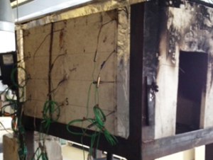
Figure 3: Locations of thermocouples in the fire box
These thermocouples will be referred as Chan in the calculations and data analyses presented in the later sections.
It is important to note at this point that the combustion box was carefully insulated and all the safety instructions and guidelines were carefully followed.
Chapter – 4; Findings
The results obtained through experimentations are presented in this section. Calculations are performed to complete the following analyses and discussion;
- Analyses of rate of consumption of material of combustion (fire burning speed).
- Analyses of temperature Variations, and flame of fire
Graphs are generated to present the changes observed and analyses of the outcomes are completed. The trends indentified through the results generated are discussed, including the details such as air flow rates, fire burning rates, and change in temperatures.
Experiment 1;
The first experiment was conducted through initiating the fire in the middle of the box. The fan was not used during this experiment; hence the forced air flow was not introduced. The enclosure consumed the natural air inside the box to complete the combustion process.
The mass compositions of the combustible materials used are as follows;
Fuel weight used = 73.8 grams
Total weight (PMMA + fuel weight) = 74 grams
The table below shows the mass consumption of flammable materials during the experiment, for every 2 minutes since the fire was ignited till it completely stopped
Table 1; Mass Consumption
Time | Mass burning (g) | Time | Mass burning (g) |
Fire start | 73 | 14 minutes | 24 |
2 minutes | 71.8 | 16 minutes | 19 |
4 minutes | 65.6 | 18 minutes | 16 |
6 minutes | 59.9 | 20 minutes | 12 |
8 minutes | 53 | 22 minutes | 9.1 |
10 minutes | 43 | 24 minutes | 5.5 |
12 minutes | 33.5 | Fire finish | 3 |
The graphical presentation of these results are as follows;
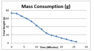
Figure 4: Mass consumption of fuel
As it can be seen in the figure above, the mass of the consumable materials decreases constantly with time. However for further investigative analyses, it is important to determine the net rate of consumption against a step-wise time interval, as it would develop understanding how the rate of mass consumption changes with time during the course of the burning process.
From these results, the rate of mass consumption was calculated in terms of grams / seconds, give as below;
Table 2; Rate of fuel consumption
Time (minutes) | Net weight consumed (g) for the interval | Rate of consumption (g/s) |
0 | - | 0 |
2 | 1.2 | 0.01 |
4 | 6.2 | 0.051667 |
6 | 5.7 | 0.0475 |
8 | 6.9 | 0.0575 |
10 | 10 | 0.083333 |
12 | 9.5 | 0.079167 |
14 | 9.5 | 0.079167 |
16 | 5 | 0.041667 |
18 | 3 | 0.025 |
20 | 4 | 0.033333 |
22 | 2.9 | 0.024167 |
24 | 3.6 | 0.03 |
26 | 2.5 | 0.020833 |
The net weight was obtained through calculating the net mass consumed during the interval period, i.e. two minutes. Plotting these values can establish the trend of the rate of consumptions, given as below;
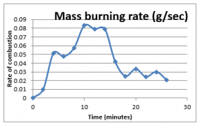
Figure 5: Mass burning rate
The figure 5 above shows the trend of rate of mass consumption from the start of the fire till it vanishes. The trend line suggests that rate of burning increases until it reaches a maximum point, after which the rate declines with the passage of time. This trend line shows that rate of the mass consumption is quite similar to the fire development chart, which has been discussed in the previous chapter. Therefore, it is possible that the temperature readings obtained during the experiments would show the similar trend, that is when the temperatures is expected to be at highest at the time when the rate of combustion material consumption is at highest.
In order to analyze the temperature recordings of the experiment, the results obtained of all the 12 thermocouples were tabulated in the form given as below;
Table 3; Form of Recorded temperature data
Date and time | Chan 1 | Chan 2 | Chan 3 | Chan 4 | Chan 5 | Chan 6 | Chan 7 | Chan 8 | Chan 9 | Chan 10 | Chan 11 | Chan 12 |
°C | °C | °C | °C | °C | °C | °C | °C | °C | °C | °C | °C | |
11/28/2013 17:35 | 17.5 | 17.5 | 17.5 | 17.5 | 17.5 | 17.5 | 17.5 | 17.5 | 18 | 18 | 18 | 18 |
11/28/2013 17:36 | 17 | 17.5 | 17.5 | 19 | 17 | 17.5 | 18 | 18 | 17.5 | 17.5 | 17.5 | 19.5 |
11/28/2013 17:37 | 20 | 25 | 45.5 | 58 | 22 | 33.5 | 48 | 52 | 21 | 23.5 | 38.5 | 66.5 |
Note: the table above does not show the complete recoding of the results, as this has been presented to establish an understanding of the form of the data recorded in this research. The same pattern was followed for all the experiments
The results were plotted against the time for each thermocouple (Chan), which is given as below;
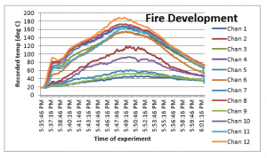
Figure 6: Temperatures during fire
The results of the temperatures obtained for all the 12 thermocouples show that the temperature raises until the fire is fully developed, before it continually reduces. This is because the rate of burning increase and reaches its peak before the rate slows down and drops to minimum, which is when the fire stops. The results also reflect the same pattern as observed in the literature review for the fire development stages (Figure 1).
The highest temperature is reached for the ‘Chan 12’, which is located at the top left corner of the of the combustion box. The obvious reason for this observation is that the burning process is at it its peak where the fresh air enters the location of the burning process. This is where the air reacts with the combustible materials to produce heat and oxides of carbon. This proves the fundamental principle in the fire engineering that the fire is dependent upon the supply of the air / oxygen.
The same observations are observed for the rest of the thermocouples installed on the box. The minimum temperature is observed for the Chan 1, which is located at the far left corner of the combustion box. The temperature observed at this point shows the minimum temperature trend, which is due to the fact that the supply of air is at its least at that location. The air which is reaches at that point is possibly already partly oxidized at the point when it reaches the Chan 1.
Another important aspect observed in the results analyses for the recorded temperatures is that the Chan 1, Chan 9, and Chan 5 produced the lowest temperature range during the experiment. This is because these thermocouples are located at the bottom of the box, which means the hot heat exhausted in the fire reaction process reaction is transferred through the convection process towards the top side of the box. Therefore Chan 4, Chan 8 and Chan 12 recorded the highest temperatures during the experimentation. It is also important to note that the ventilation process used for these experiments was natural as the forces air through fan was induced in this experiment.
Reviewing the capacity of the flame is another important factor considered in this research conducted, for which photograph was taken of the burring process. The following figures show the images of the flames after the interval of 2 minutes during the fire development stage;
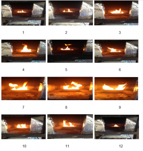
Figure 7: Images of flame during the experiment
As it can be seen from the images above, the fire flame starts slowly and grows with time. The flame reaches its peak after about 12 minutes in time (image 7), which is the point when the rate of combustion is at its peak, and so as the temperature inside the box. This is the time when the highest levels of radiations are released. It can be further noted that the flame width and height also increases with time until the fire the fire is fully developed
The results might show some variations when the air fan is switched on. Therefore the following experiments were further conducted to analyses the results produced through introduction of forced air under the same conditions.
Experiment 2;
The second experiment, the same procedure were used as in the first experiment, but with the low fan speed introduced to supply forced ait into the combustion box. This experiment took nearly 25 minutes to complete, and the fan was started after 2 minutes of the start of the experiment.
The mass compositions of the combustible materials used are as follows;
Fuel weight used = 73.50 grams
Total weight (PMMA + fuel weight) = 75.50 grams
The velocity of the wind = 1.60 m/s (through adjustment in the fan placed outside the opening of the box)
The table below shows the mass consumption of flammable materials during the experiment, for every 2 minutes since the fire was ignited till it completely stopped
Table 4; Mass Consumption
Time | Mass burning (g) | Time | Mass burning (g) |
Fire start | 75 | 14 minutes | 33 |
2 minutes (fan started) | 73 | 16 minutes | 23.1 |
4 minutes | 72 | 18 minutes | 15 |
6 minutes | 65.4 | 20 minutes | 13.2 |
8 minutes | 61.2 | 22 minutes | 8.5 |
10 minutes | 54 | 24 minutes | 7.2 |
12 minutes | 46.5 | Fire stopped | 6 |
The graphical presentation of these results is as follow;

Figure 8: Mass consumption of fuel
From these results, the rate of mass consumption was calculated in terms of grams / seconds, give as below;
Table 5; Rate of fuel consumption
Time (minutes) | Net weight consumed (g) for the interval | Rate of consumption (g/s) |
0 | - | 0 |
2 | 2 | 0.016667 |
4 | 1 | 0.008333 |
6 | 6.6 | 0.055 |
8 | 4.2 | 0.035 |
10 | 7.2 | 0.06 |
12 | 7.5 | 0.0625 |
14 | 13.5 | 0.1125 |
16 | 9.9 | 0.0825 |
18 | 8.1 | 0.0675 |
20 | 1.8 | 0.015 |
22 | 4.7 | 0.039167 |
24 | 1.3 | 0.010833 |
26 | 1.2 | 0.01 |
Plotting these values provides the trend of the rate of consumptions for this experiment, given as below;
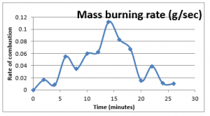
Figure 9: Mass burning rate
The rate mass burning has been compared with the other experiments at the end of this chapter.
Similarly, the temperature recordings / results obtained of all the 12 thermocouples were tabulated and the following plot was created;
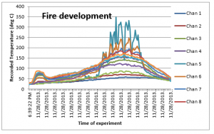
Figure 10: Temperatures during fire
The two distinct variation observed in the figure given above are; (1) there is a definite rise in the temperature as soon as the fan is tuned i.e. that is after two minutes of the start of experiment, as a clear jump is recorded for temperatures on all thermocouples, and (2) higher temperatures are recorded for Chan 5, 6 and 7. This is because the burning rate suddenly increases as soon the additional air is supplied which reacts with the combustible materials to produce heat. This then is normalized as the air is an excess and the temperature then shows a steady increase.
The middle part of the box received the highest temperature as the fire was started in the middle of the box, and through the supply of excessive air and conservable gaseous mixing due to the high velocity air, much higher temperatures are recorded in this experiment as compared to the experiment 1 where there was no air supplied through the fan. It is consequently vital to note that the varied supply of air have an effect on fire spread. Convection dominates the heat exchange to the surface of fire spread, and hence a different trend of recorded temperature have been recorded in this experiment.
The following figures show the images of the flames after the interval of 2 minutes during the fire development stage of this experiment;
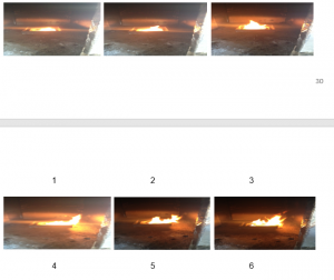
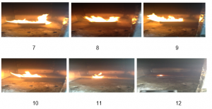
Figure 11: Images of flame during the experiment
As observed from the figures above, it can be seen that the flame shifts towards the flow of the supplies air during the experiment, which can be clearly seen in the images 7 to 9. Stronger flames are observed as compared to the 1st experiment, which again is the effect of the supplied air.
In the next experiments, higher flow rates of the supplied air will be used to further analyze the affect of air on the fire development
Experiment 3;
In the third experiment, the following mass compositions of the combustible materials were used;
Fuel weight used = 72.5 grams
Total weight (PMMA + fuel weight) = 74.5 grams
The fan was started after 2 minutes of initiating the fire, with fan wind velocity of 1.85 m/s
Similar to the previous experiments, the following shows the mass consumption of flammable materials during the experiment, for every 2 minutes since the fire was ignited till it completely stopped
Table 6; Mass Consumption
Time | Mass burning rate (g) | Time | Mass burning rate (g) |
Fire start | 73.3 | 14 minutes | 22.2 |
2 minutes | 70 | 16 minutes | 17 |
4 minutes | 66.8 | 18 minutes | 11 |
6 minutes | 62.4 | 20 minutes | 9.2 |
8 minutes | 55.8 | 22 minutes | 7 |
10 minutes | 45.4 | 24 minutes | 6.8 |
12 minutes | 34.9 | Fire finish | 6 |
The graphical presentation of these results is as follows;
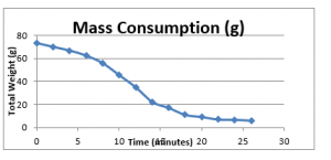
Figure 12: Mass consumption of fuel
From these results, the rate of mass consumption was calculated in terms of grams / seconds, give as below;
Table 7; Rate of fuel consumption
Time (minutes) | Net weight consumed (g) for the interval | Rate of consumption (g/s) |
0 | - | 0 |
2 | 3.3 | 0.0275 |
4 | 3.2 | 0.026667 |
6 | 4.4 | 0.036667 |
8 | 6.6 | 0.055 |
10 | 10.4 | 0.086667 |
12 | 10.5 | 0.0875 |
14 | 12.7 | 0.105833 |
16 | 5.2 | 0.043333 |
18 | 6 | 0.05 |
20 | 1.8 | 0.015 |
22 | 2.2 | 0.018333 |
24 | 0.2 | 0.001667 |
26 | 0.8 | 0.006667 |
Plotting these values provides the trend of the rate of consumptions for this experiment, given as below;
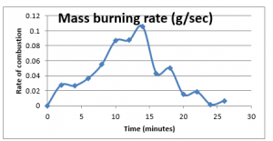
Figure 13: Mass burning rate
Similarly, the temperature recordings / results obtained of all the 12 thermocouples were tabulated and the following plot was created;
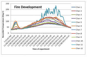
Figure 14: Temperatures during fire
The results of the experiment 3 show that these are quite similar to the experiment 2, except for the observations; (1) even higher temperatures were recorded as soon as the fan with even higher speed was started, which is because the higher air flow at the start resulted in improved reaction time and consequent heat exhaust. (2) The deviations in the recorded temperature for different thermocouples are on the lower side. This is because higher velocity of air was used, and therefore convection dominated with good mixing of the air which distributed the temperature to the surrounded thermocouples. However, as was the case in the experiment 2, the maximum temperatures were recorded in the middle section of the box for Chan 5, 6, 7 and 8.
The following figures show the images of the flames after the interval of 2 minutes during the fire development stage of this experiment;


Figure 15: Images of flame during the experiment
From the images above, it can be clearly observed that the intensity of the flame has much increased as compared to the previous experiments. The flames are wider from the start of the experiment (after 2 minutes interval), which is indicative to the fact that wind has increased the flame potential of the fire within the box. Furthermore, the flame analyses show that due to higher velocity of the supplied air, the direction of the flames is not consistent. This could be due to the fact that with higher wind velocity, there is high convectional momentum along with rapid variation of exerted pressure and velocity in both time and space.
Experiment 4;
Mass compositions of the combustible materials were used in the fourth experiment are;
Fuel weight used = 70.0 grams
Total weight (PMMA + fuel weight) = 75.5 grams
The fan was started after 2 minutes of initiating the fire, with the velocity of fan set at 2.05 m/s
Similar to the previous experiments, the following shows the mass consumption of flammable materials during the experiment, for every 2 minutes since the fire was ignited till it completely stopped, which took about 24 minutes
Table 8; Mass Consumption
Time | Mass burning rate (g) | Time | Mass burning rate (g) |
Fire start | 74 | 14 minutes | 20.9 |
2 minutes | 69.6 | 16 minutes | 14.5 |
4 minutes | 66.2 | 18 minutes | 9.5 |
6 minutes | 61.1 | 20 minutes | 7.1 |
8 minutes | 52.6 | 22 minutes | 6.2 |
10 minutes | 43.4 | 24 minutes | 5.3 |
12 minutes | 31.5 | Fire finish | 4.2 |
The graphical presentation of these results is as follows;
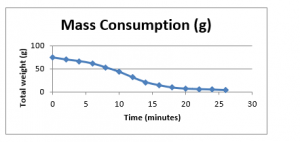
Figure 16: Mass consumption of fuel
From these results, the rate of mass consumption was calculated in terms of grams / seconds, give as below;
Table 9; Rate of fuel consumption
Time (minutes) | Net weight consumed (g) for the interval | Rate of consumption (g/s) |
0 | 4.4 | 0 |
2 | 3.4 | 0.036667 |
4 | 5.1 | 0.028333 |
6 | 8.5 | 0.0425 |
8 | 9.2 | 0.070833 |
10 | 11.9 | 0.076667 |
12 | 10.6 | 0.099167 |
14 | 6.4 | 0.088333 |
16 | 5 | 0.053333 |
18 | 2.4 | 0.041667 |
20 | 0.9 | 0.02 |
22 | 0.9 | 0.0075 |
24 | 1.1 | 0.0075 |
26 | 0.8 | 0.006667 |
Plotting these values provides the trend of the rate of consumptions for this experiment, given as below;
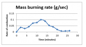
Figure 17: Mass burning rate
Similarly, the temperature recordings / results obtained of all the 12 thermocouples were tabulated and the following plot was created;
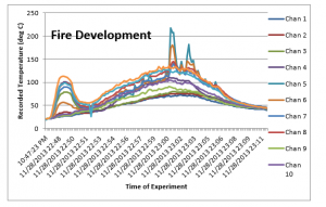
Figure 18: Temperatures during fire
The finding which we discussed for the experiment 3 are much more clear and apparent in this experiment. The initial jump in the temperature as soon as the fan is started is even greater in this experiment, which is again the effect of higher wind velocity. Similarly the increased convection rate along with the turbulent flow improved the mixing of the heat exhaust, which results in much less deviation in the installed thermocouples, which results in a more uniform temperature recordings.
The following figures show the images of the flames after the interval of 2 minutes during the fire development stage of this experiment;
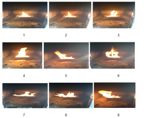
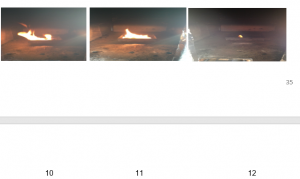
Figure 19: Images of flame during the experiment
Similar to the experiment 3, the results show that the increased velocity used in the experiment produces enhanced intensity of flames, and with high turbulence effect the direction of flames are inconsistent. The results further show that the width as well as the height of the flames also has increased due to this effect.
Now let us compare the rate of fuel consumptions for all experiments, given as below
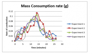
Figure 20: Comparison of mass consumption for all four experiments
As it can be clearly seen from the figure above, after 2 minutes of interval, the rate of mass consumption is; experiment-4 > experiment-3 > experiment-2 > experiment-1, which is a clear evidence of the effect of the air/wind on the fire. It further shows the experiment 4 has most consistent changes in mass consumption rates, with much less deviations as compared to the rest of experiments, which is due to enhanced mixing of reactants. The calculated rate of combustion is least for the experiment 1, which is evidently due the lack of supply of air/wind.
Chapter – 5; Conclusions
All the parameters related to the fire which have been studied in this research provide conclusive evidence that fire follows a pattern where the rate of combustion and temperature increases until it is fully developed. The fire then reaches a point when it is fully developed before the rate of combustion decreases until the fire is stopped. The results observed further indicated that the supply of air is a fundamental aspect of the combustion process, and the reaction process is derived by the ventilation process inside the fire containment box.
The gas speed and temperature inside the fire crest are mainly reliant on the measure of heat created by the fire source and the altitude over the fire source. Blending with the encompassing air expands the mass flux in the crest. The fire crest's speed and temperature increases when the fire is supplied with forced air. There were sudden jump in the rate of combustion and temperature for all thermocouples installed in the fire box, which further indicated the rates getting even higher as the wind velocity was increased with each experiment. The overall rate of reaction and fire development was also the fastest in the experiment where the supplied rate of wind was highest.
In the centre segment, the major factor is flame radiation. This is because of the fire's width expands with increasing height, and the strength of the flames is at peak in the middle of the box. Wider fire flames were generated when the excessive air at higher speed was supplied, which have more heat exchange through radiation. The heat generated is at maximum for where the fresh air is interacted with reactants, which was evident from the experiment where the recorded temperatures were highest near the opening side of the box, and lowest at the far bottom corner of the firebox.
Convection dominates the burning process, as evident from the fact the fact that with higher rate of supplied wind velocity, the rate of reaction increased. Furthermore, with higher velocity of air, the heat exhausted were thoroughly distributed and the temperature underwent much less variations. Therefore it can be concluded that the not only does the wind enhanced the burning, but it also distributed heat flux all around the experimental fie box
References
Andrews, G. E. (2007). Combustion Fundamentals. Leeds, University of Leeds.
Andrews, G. E., J. Ledger and H. N. Phylaktou,(2000a), Pool Fires in a Low Ventilation Enclosure, In Proceedings of the IChemE Symposium on Hazards XV: The Process, Its Safety and the Environment.
Backvik, B., et al., (1996). Handbook on fire protection methods for a ventilation system, ISBN 91-630-4419-6, Stockholm
Bukowski, R. and Richard, W., (1996). Modelling a back draft incident: The 62 watts street (NY) fire. Fire Engineers Journal (1), 14-17.
Drysdale, D.,(2010), The origins of fire safety engineering in the UK, In Proceedings of the Fire Safety Engineering in the UK: The State of the Art, Edinburgh, Edited by R. Carvel, Published by University of Edinburgh
Drysdale, D., (1998). An introduction to fire dynamics. New York: John Wiley & Sons.
Enclosure fires, (2001). Lars-Göran Bengtsson and the Swedish Rescue Services Agency.
Floyd, J. E. and K. B. McGrattan (2009). "Extending the mixture fraction concept to address under-ventilated fires." Fire Safety Journal 44(3): 291-300
Gorbet, G & Hopkins, R., (2007). The current knowledge & training regarding backdraft, flashover, and other rapid fire progression phenomena.
Grimwood, P., Hartin, E., McDonough, J., & Raffel, S. (2005). 3D fire fighting: training, techniques, and tactics. Stillwater, Fire Protection Publications.
Gross, D. and A. F. Robertson (1965). "Experimental fires in enclosures." Symposium (International) on Combustion 10(1): 931-942.
Gordonova, P., (1998). Spread of smoke and smoke gases via the ventilation system, Department of Building Sciences, Lunds university.
Harmathy, T.Z. (1978). "Mechanism of burning of fully-developed compartment fires." Combustion and Flame 31(0): 265-273.
Hayasaka, H., Kudou. Y., (1997). Burning rate in a small compartment fire, Hokkaido University, Sapporo, Japan.
Hull, T. R. and A. A. Stec (2010). Introduction to Fire Toxicity. Fire Toxicity. Ed. T. R. Hull and A. A. Stec. Cambridge, Woodhead Publishing Limited: 1-25
ISO/IEC Guide 52, (1990). Glossary of Fire Terms and Defi nitions, International Standards Organizations
ISO 5660. (2002). Reaction to fire tests heat release, smoke production, and mass loss rate (Cone calorimeter dynamic measurment). International Standards Organization
Janssens, M. (2002). Calorimetry. SFPE Handbook of Fire Protection Engineering. Ed. DiNenno. Quincy, Massachusetts, National Fire Protection Association: 3-38.
Jones, Walter W., G.P. Forney, Richard Peacock and Paul A. Reneke. (2000). A Technical Reference for CFAST: An Engineering for Estimating Fire and Smoke Transport. National Inistitute of Standards and Technology. Gaithersburg, MD.
Karlsson, B. & Quintiere, J.G. (2000). Enclosure fire dynamics. Boca Raton, FL: CRC Press.
McCaffrey, B.J., (1981). Quintiere, J.G., Harkelroad, M.F., Estimating room temperatures and the likelihood of flashover, Fire Technology 17 98-119 18 122.
Mcgrattan, K.B.,(2005), Fire Modeling: Where Are We? Where Are We Going, Published by International Association for Fire Safety Science.
Mowrer, Frederick W. and Robert Brady Williamson (1987). "Estimating room temperatures from fires along walls and in corners." Fire Technology 23(2): 133-145
PD 7974., (2002). Application of fire safety engineering principles to the design of buildings - Guide to design framework and fire safety engineering procedures. British Standards Institution. London
Purser, D. A. (2002). Toxic assessment of combustion products. SFPE Handbook of Fire Protection Engineering. Ed. DiNenno. Quincy, Massachusetts, National Fire Protection Association: 85-146
Purser, D.A., A. A. Stec and T. R. Hull (2010). Fire Scenarios and Combustion Conditions. Fire Toxicity. Ed. T. R. Hull and A. A. Stec. Cambridge, Woodhead Publishing Limited: 26-47
Quintiere, J.G. (1998). Principles of fire behavior, Delmar Publishers
Wade, C. A. (2004). A User's Guide to BRANZFIRE 2004. Building Research Association of New Zeland. Wellington.
Walton, W.D. (1985). ASET-B A Room Fire Program for Personal computers. National Bureau of Standards. Washington, DC.
Yung, D. (1991). "Small-scale compartment fire experiments with PMMA cribs." Fire Safety Journal 17(4): 301-313
Get 3+ Free Dissertation Topics within 24 hours?


