Comparison of Timber and Steel Framed Buildings
January 28, 2021
Technical details of runway layer works, compared to roads
January 28, 20211. Executive Summary
Proposals have been prepared for the developer for the internal layout and fitting out of building on the proposed site at Woodland. Internal space layouts/drawings for two floors and the design of service lines have been included. The designs are engineered such that the building occupants are provided with safe exit routes, state of the art air control system, ventilation system, daylight and other services.
The design includes key floor plans showing positions of vertical service risers, horizontals services distribution, and cross section at critical junctions detailing construction and enclosure details. Technical description of the services has been provided; including vertical transportations systems has also been discussed.
A technical description of the safety in plan for the building has also been proposed in the report. Various safety measures are discussed and proposed, with details of its requirements and its applications.
2. Introduction
In order to meet official, physical and cultural requirements and to provide a safe working environment to all the residents, the building must be properly designed (Christian, 2008). It is necessary to engineer the building designs to produce the best possible outcome from the given resources. A good office building layout not only enhances productivity, but also increases the chances of increased profits for the developer.
(Note: The references for this proposal were mainly consulted to get general understanding of the design, planning and construction principles.)
3. Proposal Description
As per the client’s request, proposals have been prepared for an internal layout of two floors including all the service requirements of the subject building. The preliminary layout design can be used to work out the integrated design of the building, once the order has been matured.
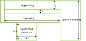
Following is the given Layout of the proposed building with all dimensions in meters. The site has been divided into 4 sections, that are (1) Central Portion, (2) Upper wing, (1) Lower wing and (4) Lower wing extension (as shown in Fig-1 below)
Figure-1; Floor Plan of proposed Building
(Dimensions in meters for internal spans given, considering 1 ft wall thickness)
4. Proposed Layouts
Following are the detailed drawings of the proposed building layouts. The partitions used in this proposal are viva wood cement board using stainless steel panel frames for easy installations and removal. The design would provide the developer the flexibly to change the internal layout designs as per his/her requirements in the future. Furthermore, the viva boards have been used as these are produced by mixing of wood-particles, cement and various mineral agents. These boards provide fire protection to the building due their high fire resistance value
Figure-2; Floor Plan of proposed Building
(Dimensions in meters for internal spans given, considering 1 ft wall thickness)
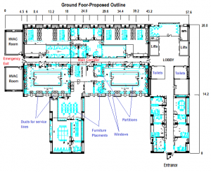
As it can be seen from this diagram, the entrance to the building has been proposed in front of the main road as it can give an easy access to the building occupants. The proposed plan is completely compatible with the means escape (two escape routes, wide main corridor for emergency use), circulation (state of the art ducting systems) and maximum daylight usage (pair of windows adjacent to every service ducts). The internal layout includes closed rooms for meetings and manger rooms, open working spaces along the walls and large conference rooms. These placements have been engineered to maximize internal space utilization factor
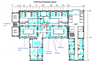
Figure-3; Floor Plan of proposed Building
(Dimensions in meters for internal spans given, considering 1 ft wall thickness)
5. Service Lines Design Proposals
5.1 Vertical Service Risers
Providing sufficient vertical risers hold a key importance in the design of the building. In this proposal, comprehensive vertical risers are designed for the subject building. These risers are located at the front and back of the subject building, seven in numbers on each side. The risers are referred to as ducts in the text that follows.
These ducts are designed such that they become an integral part of the overall building design and outlook. The size of these ducts are 2.4m (length) by 0.4 m (width), providing more than sufficient space for all the required services for the building. These ducts can be used to connect central air-condition (HVAC) and exhaust system for the building. Furthermore, these can provide natural ventilation systems across the floor of the building; to provide thermal comfort for the residents
This service shall also accommodate the above water drainage lines. Details of specifications are in the later part of this report
Figure-4; Building vertical Service Risers
(Dimensions in meters, Aerial View)
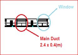
Figure-5; Building Vertical Service Risers
(Dimensions in meters, Horizontal View from outside)
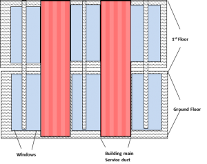
The proposed vertical section of the building is composed of main building ducts along with the window panels, as shown in the figure above. This design would enable the developer to utilize these large ducts for any service requirements in the future. In this design, these passage ways will be used to install services lines required for electric power cables, hot and cold water supply, drain lines, and as means of providing ventilation.
The building drainages system and water lines can be connected from the point of use to these ducts, and then connected to the underground main drainage line or the main water supply line. A 6 inch UPVC pipe shall be sufficient for drainage connections and a 2 inch brass pipe for the water supply line.
5.2 Horizontal Service Distribution
The Horizontal distributions of services are designed to expand through the top of roof ceiling, to be installed on roof walls. Approximately 1 meter of width has been provided for easy installations and access, as shown in the figure below. This space shall be sufficient to provide the complete air control system ducting throughout the floor(s). The detailed diagrams of the proposals are presented below in the Figure-5 and Figure-6
Figure-6; Building Vertical Service Risers
(Dimensions in meters, Horizontal View from inside)
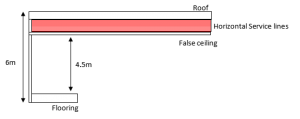
The figure below illustrates the horizontal hot and cold water service lines, HVAC ducts and lines, diffusers and exhaust facility. Along these lines, Stainless steel cable trays shall also be installed for electric lightings and other electric installations
Figure-7; Building Vertical Service Risers
(Dimensions in meters, Aerial View)
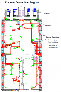
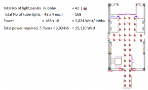
Figure-8; Building Lighting
(Dimensions in meters, Aerial View)
6. Performance Specifications
|
Element |
Detail |
|
Sub structure |
Deep strip Concrete foundations. Pressed concrete Beam and block flooring (140 mm deep beams, 425 x 205 x 95 block-size), greater than 7.3 N /mm2 compressive strength, iso rubber for sound minimisation and air tightening, thermal floor slab insulation. |
|
Main structure frame |
Strong load bearing block-work (150 mm deep beams, 435 x 205 x 95 clock-size) |
|
Main structure floor(s) |
Partitioning structure, pre-cast strong concrete (thermal 70 mm floor-slabs approx) |
|
Main structure--roofs |
Concrete roof-tile (415 x 325). Mono plymembrane system, highly compression resistant. |
|
Main structure; stairs |
MS quality balustrades with Pressed concrete for stairs and MS quality handrails welded or screwed (260 mm going minimum, greater than 60 N/mm2 strength) |
|
Walls: external |
Facing Brick; weather-proof, low-maintenance, through colour. 95 x 205 x 95 block-size, 45 mm insulation, |
|
Windows/doors: external |
Double glazed, self cleaning, e-coated, tough, Aluminium ( 60mm frame, reversible, energy efficient) windows, ply wood or metric-timber doors (fine finish) and aluminium entrance doors/gate (70mm frame, reversible, energy efficient) |
|
Finishing internal walls |
Dorr leaf mould-panel, 2010 (H) x 875 (L) x 45 (W) mm, 30-S Fire rating, Stud portioning, MDF moulding, walls interior painted |
|
Finishing internal floor |
Wood-grain structure, 8 mm, fully carpeted with underlay and grips. |
|
Finishing internal; ceilings |
Concealed grid-metal frame; suspended ceilings system, high quality viva wood cement board |
|
Fittings accessories and equipment |
Durable high quality fittings for kitchen with chromed taps in kitchen and toilets |
|
Miscellaneous services |
Powder coated white sanitary pipes and bends (all lengths), waste pipes for water line, 24 hrs hot and cold water supply, HVAC Units (2), modern boilers for central heating, state of the art ventilations system (controlled), three phase voltage supply, built in alarms systems (doors, smoke, heat etc), and other services will be made readily available to residents. |
7. Vertical Transportation
The vertical transportation of the building is composed of the following
- Lifts; provide the most efficient and attractive method of the building vertical transportation. Four lifts shall be installed in the building, of which three shall be for passenger usage (20W each) and one shall be the service lift (25W). the positioning of the lifts can be seen on the proposal layouts. Space allocation for each lift is 2.5m x 6m
Figure-9; Building Lifts
(Aerial View)
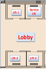
- Stairs; provide the most economical and safe passage for vertical transport. Two stair systems have been proposed for the building, each with staircase of 3 meter width.
8. Fire Prevention
Fire-protection applications and the related fire-protection strategies are of key importance to any building (Longman, 1999). Safety is an integral part of the modern world building designs and the Engineers, designers and developers around the word have developed key procedures that can help in designing active and passive fire protection systems
8.1 Passive Fire Precautions;
The fire strategy is designed to fulfil and achieve the objectives of the various hearth building laws. The multi use building shall be equipped with at least two fire escapes in the building. Entrance to the fireplace escapes should be protected by locked doors that are preferably fire resistant (NFPA 101).
Distance for travel to the hearth exits is calculated based mostly on the occupant load and also the expected time for evacuation. The exit widths are designed to be large enough (3 meters) to evacuate the load of occupants. Fire fighting equipments such as fire extinguishers, Sprinklers and hearth doors will be installed in the building. The structure is designed to resist intense fires and have a few hours fire resistance rating; through the use of fire resistant material of construction (please refer to section 6 for details)
Fire trucks can get a clear access to the central building in case of fire breakout (main entrance designed on the main road end, see Figure-2), sufficient space for a fire truck to adopt a hardstand position from where the fire can be doused has also been provided.
8.2 Active Fire Precautions;
The following active safety fire protection systems/tools and equipment are used for this buildings;
- Smoke detectors/Alarms; used to detect smoke from suspected fire source and are used to alarms the occupants of the potential hazard
- Fire alarms; used to alarm/alert the occupants
- Fire extinguishers; to extinguish small fires.
- Automatic sprinkler ion; used to extinguish fire once activated
- Voice communication system; enables to communicate and alert
- Messages and instructions; guides residents in the emergency situation
- Fireproof lift systems; this ensures that the users that the lift are not stuck/injured inside the lift
- Protected corridor and exit doors; ensures that the residents find a safe passage out
- Fire hydrants; provides water to fire extinguishing team
- Fire bucketsor fire hoses; can be useful to eliminate small fires
The work drawings/plans have been prepared in-accordance with the Building Regulations and special consideration has been given to the part-B regulations of fire safety. However, the final design proposal will cover all the main safety aspects of the building in details; such as distance of each room to the point of safety, stair widths, escape routes and the fire protections systems.
9. References
Addison-Wesley Longman, Harlow Hall, F & Greeno, R 2009 Building Services Handbook (5th ed.)
Addison-Wesley Longman, Harlow Dean, Y, 1996 Mitchell's Finishes (4th ed.)
Addison-Wesley Longman, Harlow Reid, E 1998 Understanding Buildings
Butterworth- Heinemann,. Oxford McEvoy, M 1994 Mitchell’s External Components
Christian Muller, Matthias Oppe., 2008, Conceptual design and design examples for multi-storey building Dissemination of information workshop
EIA (Energy Information Administration). 2002. 1999 Commercial Buildings Energy Consumption Survey (CBECS). (http://www.eia.doe.gov/emeu/cbecs.contents.html
Hopkinson, R. G., P. Petherbridge and J. Longmore. 1966. Daylighting. London,
Heinemann Monroe, Linda K. 2002. "Problem-Solver." In Buildings. February 2002.
Longman, Harlow Stollard, P & Abrahams, J 1999 Fire from First Principles (3rd ed.)
NFPA 101. 2000. ‘Life Safety Code.’ National Fire Protection Association, Quincy, MA.
Pacific Gas & Electric (PG&E). 1997. Commercial Building Survey: Summary Report to the California Energy Commission. Draft 4.03.
SFPE. 2000. SFPE Engineering Guide to Performance Based Fire Protection Analysis and Design of Buildings.
SFPE. 1995a. The SFPE Handbook of Fire Protection Engineering, second Edition
SFPE. 1995b. The SFPE Hand book of Fire Protection Eng, second Edition. 3-78 - 3-79
Get 3+ Free Dissertation Topics within 24 hours?


