
Dissertation Proposal – Student Submitted
January 30, 2021
Limit State Design of Structures
February 1, 20211. Introduction
There are more than 50,000 materials available to be used in engineering services. The selection of material while designing a structure greatly depends upon their physical properties. Mistakes in the selection of right material can cause disaster. The appliances which are poorly designed can be investigated for their excessive give which may occur because of the absence of the low modulus of the engineering material. Many of the engineering appliances and structures are made up of the alloys and metals (Loveday, 1996, 1992). Consistent research has been carried out throughout the world for the development of the emerging engineering materials which may be used to construct heat engines with high efficiency, low friction bearings and many more. There is a set of attribute linked with each material (Abrao et.al., 2007; Marta and Chris, 2006). Therefore we can say that the properties are important while selecting the material rather than material itself. The important properties include strength, density, toughness, modulus and thermal conductivity (Bell and Stephanie, 1999). In this report laboratory results of a wide range of materials are presented. These results will be used to understand and develop the capability and scope of the engineering material system and manufacturing processes. Different groups of the materials are considered to understand their and categorize their physical properties. The data obtained is related to the theoretical description of each material type and their expected physical properties.
1. Aim
The basic aim of this laboratory report is to investigate and understand the physical properties of engineering materials and the impact these have on manufacturing processes.
2. Hardness test
Hardness of the four separate specimens is determined y using Brinell hardness testing machine.
Hardness of the three separate specimens and three reinforced composite material is determined by using Brinell Hardness Testing Machine. The specimen size used here is a circular rod of length of 65mm and the diameter of 35mm. The specifications of the machine are ball intender of diameter 20mm and the maximum load of 4000N (Chandramohan and Marimuthu, 2010).
2.1. Procedure performed
The machine used to perform the hardness test of the selected materials is illustrated in figure 1.
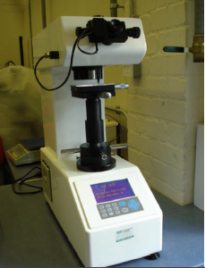
Figure 1: hardness test machine
The machine was switched from the rear side of the machine as shown in figure 2.
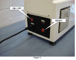
Figure 2: rear side of the machine
The reset button was then pressed after 5 seconds approximately.
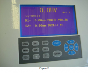
Figure 3: front buttons
After resetting the machine, the setup button was pressed from the front of the machine as shown in figure 4.

Figure 4
After selecting the force unit the OK button was pressed as shown in figure 5.

Figure 5
The hardness scale was selected to HV and then the OK button was pressed as shown in figure 6.

Figure 6
The brightness of the LCD was adjusted and OK button was pressed.

Figure 7
Date and time was adjusted as shown in figure 8.

Figure 8
On the side of the machine the test force was selected by moving hand wheel as shown in figure 9.

Figure 9
The duration of dwell time was then selected, as shown in figure 3 the dwell button was pressed. The 5 second steps were chosen and then OK button was pressed. The dwell time duration was selected for each material. The test specimen was then placed on the bed of the machine as shown in figure 10.
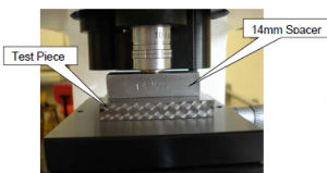
Figure 10
The spacer of about 14 mm was placed on the top and then wind up to the barrel of the microscope as shown in figure 10. The machine was allowed to go through the cycle after removing the spacer and pressing start button.
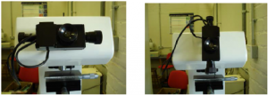
Figure 11
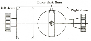
Figure 12
Eye piece of the machine was used to investigate the material properties as shown in figure 11. The indentation was focused by the movement of the inner lines to the corners indentation as shown in figure 12. Enter button was pressed. The eye piece was turned 90o as shown in figure 11. The test piece was moved slightly and the procedure was repeated. The print of test results was taken out of the machine.

Figure 13
2.2. Calculations
The specimen data is illustrated in table. The machine has the ball intender with the diameter of 20mm and maximum load of 4000N. The BHN of all specimens can be calculated by following formula
P - Load applied to the specimen.
A - Area of the indentation.
P =294.2N.
Where,
D - Diameter of the ball intender.
d - Diameter of the indentation.
BHN = P/A
3‑1 calculations
Material | D1 | D2 | Load duration | H1 |
Cast steel | 5.5 µm | 18.60 µm | 15 | 383051.3 |
Brass | 165 µm | 167.6 µm | 15 | 2011.16 |
Spring steel | 43.50 µm | 5 µm | 15 | 94581.8 |
Aluminum | 248 µm | 162 µm | 15 | 855.4 |
Material | BHN |
Cast steel | 511 |
Brass | 358 |
Spring steel | 373 |
Aluminum | 355 |
2.3. Results
Results show that cast steel is the least hard material while brass is the most hard material.
3. Tensile test
The loads causes the material failure is dependent upon the material properties and the value of the load applied through machine. In this section tensile tests have been performed for carbon steel, brass and aluminum.
3.1. Procedure performed
The machine and computer was turned on. QMAT software was used. After entering data the machine was set to zero graphs were plotted.
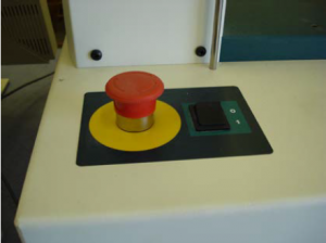
Figure 14

Figure 15 material selection

Figure 16 selection of stress range
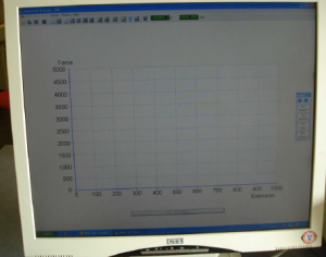
Figure 17 enter graph data
3.2. Tensile test machine

Figure 18 Tensile test, machine
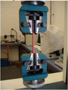
Figure 19: tensile test, machine
The top jaw of the machine was moved up and down by pressing arrows. The machine was then stopped by pressing circle from the center. Test specimen was selected after turning glasses on. The specimen was stretched up by machine to its stretching point. The graph was recorded and printed.
4. Material specimen preparation
4.1. Equipment
Specimen Mould, Release Agent, Mixing Cup, Mixing Stick, Cold Mould Powder and Cold Mould Liquid
4.2. Operating procedure
The release agent was used to spray the mould. Quick set was mixed by using 2 parts of the cold mould powder and 1 part of the cols mould liquid. Solution was stirred and a creamy paste was developed. Specimen was placed in mould which was filled with the solution mixture. The mixture was then left for 20 minutes and then specimens were removed. The face of the specimen was polished by starting from the rough grit to the ultra fine portion.
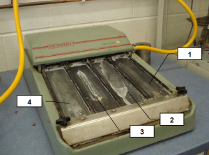
Figure 20 polishing
Four manual polishing strips
- 220 Grit
- 320 Grit
- 400 Grit
- 600 Grit
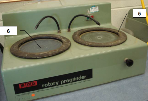
Figure 21: rotary polisher
- 800 Grit
- 1200 Grit
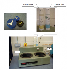
Figure 22: rotary polisher
- Spray disc with 6 micron spray before polishing
- Spray disc with 1 micron spray before polishing
4.3. Results
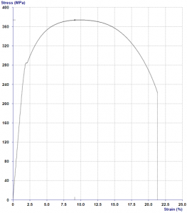
4.3.1. Product: carbon steel
5‑1 Carbon steel specimen
No. | Thickness (mm) | Width (mm) | Yield stress (MPa) | Tensile stress (MPa) | Elong at break % |
1 | 4.500 | 4.500 | 373.7 | 373.7 | 21.33 |
4.3.2. Product: Aluminum
5‑2 Aluminum specimen
No. | Thickness (mm) | Width (mm) | Yield stress (MPa) | Tensile stress (MPa) | Elong at break % |
1 | 5.000 | 5.000 | 207.9 | 207.9 | 17.36 |
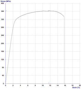
4.3.2. Product: Brass
5‑3 Brass specimen
No. | Thickness (mm) | Width (mm) | Yield stress (MPa) | Tensile stress (MPa) | Elong at break % |
1 | 5.000 | 5.000 | 362.4 | 362.4 | 15.78 |
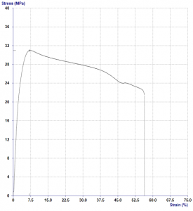
4.3.4. Product: propylene
5‑4 propylene specimen
No. | Thickness (mm) | Width (mm) | Yield stress (MPa) | Tensile stress (MPa) | Elong atbreak % |
1 | 4.000 | 10.00 | 30.97 | 30.97 | 56.4 |
5. Discussions and conclusions
Chemical treatment of the materials was helpful to remove the moisture content and thus increasing the material’s strength. The flexural rigidity of the material also has been reported to be increased by the mixture treatment of the specimens. The mixture treatment is also helpful in clearing the impurities that may adjoin the fiber material. The treatment procedure is used to stabilize the orientations of the internal structure of the material.
Results for the tensile tests of various materials have been illustrated in the form of graphs. Better results have been observed from the hybrid composites. The graphs taken for aluminum, brass, propylene and carbon steel are shown in the report. Propylene has maximum percentage of elongation which shows the material is less likely to be brittle. The percentage elongation of the aluminum is higher than brass which shows brass has a brittle like failure mechanism. The Carbon steel is a material which has a percentage elongation within the range of partial brittle materials. The elliptical cracks with their rapid propagation have been observed while testing. The tensile strength has been found to be reduced as a result of the lesser pull out of the material fibers. The higher percentage of elongation for propylene has justified the condition of the tensile strength reduction. Carbon steel’s percentage elongation also justified the condition after propylene. More material fiber pulls out was observed as a result of the material deformation. The condition has been justified by the propylene and carbon steel which has higher percentage elongation. Aluminum and Carbon steel showed partial brittleness because of the value of the percentage elongation. Thus results and discussions have shown that the carbon propylene is a better material in terms of strength when compared with aluminum and brass.
References
Abrao, A.M., Faria, P.E., Campos, J.C., Reis, P. and Paulo, J., (2006). Drilling of fiber reinforced plastics: A review Elsevier - Journal of Materials Processing Technology 186 pp.1–7
Bell, J. and Stephanie, H. (1999). A beginners guide to uncertainty of measurement NPL Good Practice Guide No. 11, pp.1386-6550
Chandramohan, D. and Marimuthu, K., (2010). Thrust Force, Torque In Drilling The Natural Fiber Reinforced Polymer Composite Materials And Evaluate Delamination Factor For Bone Graft Substitutes -A Work of Fiction Approach, submitted to Proceedings of the International Journal of Engineering Science and Technology, Vol. 2(10), pp - 6437-6451.
Hanna, T.H. (1982). Foundations in Tension, Ground Anchors, McGraw-Hill Book Company, Inc., New York, N.Y
Loveday, M.S., (1996). Creep Testing: Reference Materials and Uncertainty of Measurement in The Donald McLean Symposium - Structural Materials: Engineering Applications Through Scientific Insight. Ed. E D Hondros & M McLean, Pub: Inst. of Materials, London, pp. 277-293
Loveday, M.S., (1992). Towards a tensile reference material, Chapter 7, in Harmonisation of Testing Practice for High Temperature Material', Ed M S Loveday and T B Gibbons, Pub, Kleuwer (formerly published by Elsevier Applied Science) pp.111-153
Marta, F. and Chris C. (2006). Drilling of carbon composites using a one shot drill bit - Part II: empirical modeling of maximum thrust force, Elsevier - International Journal of Machine Tools & Manufacture 46, pp.76–79.
Get 3+ Free Dissertation Topics within 24 hours?


