
Developing Strategies to Reduce Energy Consumption
January 28, 2021
Professional Development Action Plan
January 30, 2021Introduction
The efficient use of energy has always been desired in all industrial operations. The effective and efficient use of the available energy sources can be conducted through energy audits. Conduction of energy audits for bigger facilities of industries or manufacturing units requires more effort than the smaller facilities at commercial level. Considering the complexity of the operations and equipments used in industrial energy audits, the procedures are found to be tough than the energy audits conducted in large buildings. In this report industrial facility of a waste water treatment plant has been selected as an industrial asset. A comprehensive energy audit has been conducted on the chosen industrial facility. The areas of potential problems are identified and solutions are presented in this report. Numerous methods of energy audit are explained and a specific approach has been selected to address the potential problems. The equipments used in the selected industrial facility are listed. The energy demand and consumption of these equipments have been estimated by using the data collected at the facility including operating hours, equipment rating and energy consumption. For the lost of ECM (energy conservation measures) an energy balance has been developed. The energy streams are considered as discrete functions by selecting at least two categories of the energy conservation measures. As a first step energy consumption data of the system was obtained. The factors affecting the consumption trend are identified and listed. The efficiency of the system was improved by the correct identification of the economic opportunities. Based on the results of the energy audit for the selected facility the report was enclosed by the concluding remarks and few recommendations.
Background: Energy
There are many form of the energy which are inter-convertible and changed to the forms that are useful for doing work. The two most common forms of energy include potential energy and kinetic energy. The capacity of doing work is usually termed as a potential energy and the conversion of this capacity to the work or motion is called kinetic energy. The major source of the convertible energy is fossil fuel. These fuels are burned for the production of heat that can be used to accomplish a given task. There are various units of the energy the most common are kilowatts-hours and Btu for electrical energy and heat energy respectively (Christopher, 2010).
Energy Audit
The flow of energy in any process or building can be assessed under the heading of energy audit. The procedures can present numerous ways to reduce the energy consumption throughout the process. Energy audits are usually conducted to evaluate the efficiency of the industrial facilities for consuming energy and providing comfortable environment. Energy audits has become an important part of our lives as energy is required in every aspect of ongoing processes including lights, cars, make products, heating, air-conditioning etc. With the growth in the economies energy demands increases for the continuous use of modern appliances (Asian, 2008).
Preliminaries of an energy audit
The energy audit requires few preliminary measures to adopt before direct conduction of the process.
Surveying the staff of the concerned facility is important before proceeding with energy audit process. The major areas of the standard comfort are required to be addressed same as the complaints after conduction of energy audits. For example we can take the case of overheating that causes opening the windows. Such issues can be addressed to conserve energy that follows the audit procedures (Jeremiah et.al 2012).
Types of energy Audits
There are three levels of the energy audit including
- Level 1 called walk through audits which deals with the facility tours and visual inspections.
- Level 2 or Standard Audit which deals with the quantification of the energy consumption and losses through review systems, operational characteristics and thorough inspection of the equipment systems
- Level 3 or Computer Simulation which presents the detailed energy consumption in terms of functions and comprehensive evaluation of the used patterns (DAMODARAN et.al, 2012)
Phases of Energy Audit
Depending upon the complexity of the process the energy audit has three phases.
- Investigation Phase
- Monitoring Phase
- Analysis & Reporting Phase
Investigation phase
The investigation phase of the energy audit process involves the gathering of relevant data. The general data include the historical data of energy consumption, the contracts related to the energy supply and tariffs, data related to the productions levels, number of staff and areas of floor, data about occupancy hours, data of costs related to the levels of benchmarking and industrial energy usage, data about the equipments of gas metering and sub- electrical equipments, data about the consumption of the air conditioning or heating, configuration data of lighting i.e. ballast type, lamp number & fitting type and Wattage, data of compressed air systems i.e. air leaks, hours of operation and rating, data of hot water and steam boilers, data of control strategies and systems of building management, data of shading, insulation levels, orientations and building envelopes and data related to the plans of asset management (Dora, 2009).
Monitoring Phase
Detailed information of the overall site along with the major categories of energy consumption is required in this phase. The key equipments and plant operation will be inspected. The phase also includes appropriate measurement of the wide range of parameters including gas loads and electrical profiles, rates of ventilation, humidity, internal temperatures, and analysis of the boiler flu and various levels of the light (Carlos. 2010).
Monitoring Procedures
There are many monitoring procedures used to efficiently monitor the energy consumption in industry. Usually these procedures base on the invoices of the energy audits that are conducted in previous year. These procedures have three main objectives including
- Provision of the detailed audits each year
- Provision of energy data to be consumed at specific periods and points which is required for the establishment of the variations and energy patterns
- Provision of data for the continuous monitoring of the performance of ongoing processes
Energy audit instrumentation
The instrumentation of the energy audit is conducted for the following purposes.
- Light level meter
- Electric meters –voltage, current, power, energy, power factor
- Temperature - measurement
- Combustion efficiency
- Air flow and air leak measurement
- Thermo-graphy
- Data logging
Analysis and Reporting phase
The analysis and reporting phase include the overall efficiency of energy consumption per year to be determined, the analysis of the tariff, analysis of the energy saving measures on the basis of the life cycle cost, emission index of the greenhouse gases and green star ratings determination and written or verbal reports based on the findings of the energy audit processes (Carlos. 2010).
Certified Energy Manager Program (CEM)
The association of the energy engineers in USA has started the certification program in 1981. The program has offered a broader learning on the latest techniques, strategies and procedures for the reduction of energy consumption and its cost.
Pre-site work
Conducting an Energy Audit
For the construction of the water infrastructure an act was passed by congress in 2009 which was called the American Recovery and Reinvestment Act. A funding for the protection of environment was assigned. Under this act the sustainable practices of water infrastructure are required to be developed in order to enhance the green infrastructure, energy efficiency, water efficiency etc. This report has been prepared to conduct the energy audit for the water division of the island of Hawaii. The Hilo waste water treatment plant is considered as an industrial asset for which an energy audit is being conducted (Hilo, 2011).
Facility description
The waste water treatment plant is located in Hilo city of Hawaii. The exact location of the plant is the northeast shore of the Hawaii Island. Figure shows the vicinity map of the facility for its exact location.

There are three process areas of the waste water treatment plant including areas of solid handling, primary treatment facility and secondary treatment facility. The ocean outfall is being used by the plant to discharge the effluents. The sewage from the service area is usually collected and transported to the vicinity of the waste water treatment plant by using pump stations and gravitational systems. The Hilo Bay has also a part of the plant’s service area and thus the waste collection system is also located below the elevation of the ground water. The infiltration and inflow impacts are the attributes of the service area. It was 1993 when this industrial facility was constructed and has been followed by many up gradation and rehabilitation projects in last decade (Howells, 2006).
Site visit work
Operating schedules of the facility
There about 18 employees working on plant on the basis of full time operation. The typical operation time of the plant is 7:00 a.m. -3:30 p.m., from Monday to Friday. Half of the employees also take shift on Saturday and Sunday for loading and unloading operations. During the evening hours the operations are usually on standby mode.
Ongoing processes
There is a capacity of about 5 million gallons/day which has been assigned to the primary and secondary processes. The flow of the plant and major ongoing treatment processes are described in the figure. The plant has been designed for the process of Fixed Film secondary treatment.
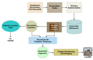
Figure 1: plant flow diagram
Figure shows the processes conducted in waste water treatment plant in detail. Pump station are used to enter the waste water into facility.
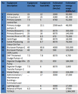
4‑1 Equipments involved
Post site work
Utility Analysis
Current Utility Use
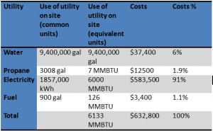
There are four types of utilities billed in Hilo waste water treatment plant including fuel oil, water, propane and electricity. The bills and utility usage was reviewed for 2010-2012.
The usage of utility per year is illustrated in following table
4‑2 annual utility usage
The summary of electricity usage is presented in table. The electricity was purchased from HELCO for the operation of Hilo waste water treatment plant (HELCO, 2012).
4‑3 billing period with cost
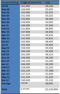
The total demand charges in above table illustrate the demand charges with all the charges that are being influenced by the peak demand of the monthly billing.
To give the instantaneous feedback following figure represents data of electrical energy with the trend of minute interval demand.
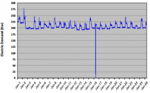
Figure 2. 15 minute interval demand of electrical energy
The measured demand can be controlled from this information. The monthly peak 15 minutes interval demand has been used to determine the 12 percent of the electrical costs of site.
Electricity Rate Schedule
HELCO is the source from where Hilo wastes water treatment plant purchase electricity under the tariff schedule of P for the operations of large power consumption.
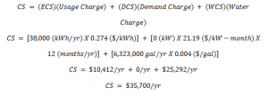
The rate of the use of electrical energy has been determined to be $0.273 which was calculated by using costs and energy consumption data of plant of recent year (2012). The demand rate of energy has been determined which is $21.19/kW/month by using the energy cost and demand rate of the plant for the same year. These values will be used for the calculation of the cost impacts of the conservation opportunities of energy in later sections (Victor, 2012).
The rates of the electricity energy bills of the plant are described in the following table for the year July 2011 to June 2012.
4‑5Monthly Electrical Energy Use and Demand Rates Utilized for ECO Cost Impact for the Site
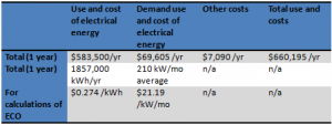
The rate schedule has been broken down in following charges
Customer Charge
A fixed fee of $385/month is charged
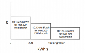
Energy Charge
Energy charge follows a declining block charge trend in which each preceding year has lesser energy charge than that of the block before it. Energy charge is measured in per kWh/month/kW of billing demand per kWh (HELCO, 2012).
For example total energy charge for a site consuming 150,000 kWhs/month with a demand bill of 250 kW can be calculated as follows

Demand Charge
The maximum average load measured in kW with the time period of 15 minutes is called demand charge. This is a declining block charge which has a billing demand of $11.25 per kW for 0 and 500kW. The billing demand will be $10.75 per kW for above 500kW. The plant has demand between 250-270kW which shows the billing demand of $11.25 per kW.
Power Factor
The power factor of 85% has been made the basis for the calculation of the demand and energy charges. The plant is working on high power factor which normally ranges from 97%-98% for which they have to pay extra $400-$500/ month.
Interim Rate Adjustment
A 10.8% increase in the amount has been added in the bill since 2010. The charge has increased the bill by about $2,600/ month.
Public Benefits Fund Surcharge
Total percentage of energy used is calculated under this heading and expressed in kWh. For 2012 the rate has been taken as $0.1015% /kWh. Monthly bill has been observed to be increased by about $150/ month.
Energy Cost Adjustment
The factor is charged according to the energy used per month. The average of this charge is about $0.08/ kWh for 2012.
Integrated Resource Planning (IRP) Cost Recovery
The other and planning costs are charged by this factor and increases bill by about $175/ month.
Energy Baseline
The plant’s energy use for the period of 12 months from July 2011 to June 2012 is illustrated in following figure.
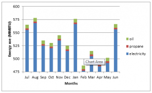
Figure 3: Breakdown of total energy use
The total energy cost of the plant is shown in the figure 4.
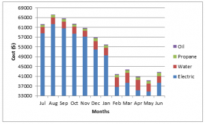
Figure 4: total breakdown of the cost of water and energy
The electrical energy cost of the plant is shown in the following figure. Figure shows the demand cost is about 12 percent of the electricity bill/month on average.
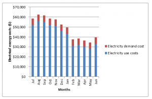
Figure 5: cost breakdown of electrical energy
Energy Conservation Opportunities
ECO 1 – operation of odour control fan during dewatering process
Recommendation
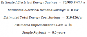
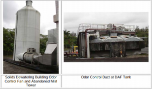
Considering the odour control system of solid processing the performance of the attached ventilation fan can be improved. The energy used for solid dewatering can be reduced. Fan can be started before dewatering process and keep turned on after one hour of the process. The related terms are calculated as below.
Background
It was 1995 when the area of the solid processing was designed with the specialized odour control system through mist towers. The fan is 15hp and has constant speed. Fan takes electric load of 76200kWh by working for 8760hrs/year. A dissolved air flotation unit is attached to the fan. Now the DAF is used as a holding tank. The operation of solid processing takes 12 hrs per week and are carried out on Monday and Thursday for 6 six hours each.
Cost and energy savings (estimated)
Odour control fan consumes about 76,200 kWh annually. Allowing fan to be operated only during dewatering operation will save the time from 168- 14 hrs/week. The energy consumption will be reduced from 76,200kWh/yr to 6,350 kWh/yr which shows about 70,900 kWh/ year of energy savings.
The sum of the ECS (electrical energy cost) and DCS (demand cost savings) is shown in terms of the CS (total estimated annual Cost Savings). The data is collected from HELCO for 2011-2012.

Implementation Cost and Payback (estimated)
The preliminary estimated cost for the implementation of above ECO $0. The manual shutdown of this equipment is possible. The payback period is 0.0 years.
The ECO can be implemented by
- Isolating ductwork of DAF from odour system
- Modification of the solid processing operating procedures and confirmation of the ventilation system shutdown
Such implementation has been estimated for about $5,000-$7,500.
Plant Impact
The plant suffering requirements are not anticipated by the above ECO implementation. The added step to the centrifuge operation can be found to turn the odour control fan on and off.
ECO 2 – elimination of tanks
Operation of sludge pumps
Recommendation
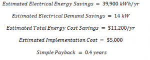
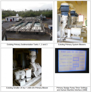
One of the primary tanks is recommended to be removed. The sludge pump timer can be optimized.
The calculations are as below
Background
The tank has loading rate 1.67 mgd. Total plant capacity is 5.00 mgd which will be reduced to 3.33 mgd by removing one tank.
Energy and Cost Savings (estimated)
A sludge collector and a cross collector operate for 8,760 hrs/year. The electrical loads are 0.527 kW and 0.527 kW for 80% load factor and 85% motor efficiency respectively.

Implementation Cost and Payback (Estimated)
For the implementation of this ECO the total estimated cost is $5,000. The payback period is 0.4 years.
The ECO can be implemented by
- Isolation of the one of the primary tanks
- Draining, cleaning and filling of the tank with effluent
- Cycling of the helical skimmer, collecting motors and sludge pump with the frequency of 15min/week.
Plant Impact
The plant staffing will not be affected by the implementation of this ECO.
ECO 3 – management of the electrical demand
Recommendation
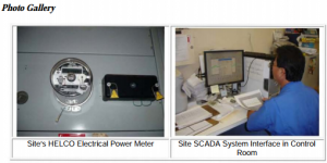
Investment in onsite monitoring of electrical systems is recommended.
Background
Plant has one meter of electricity. There are two ways which affect the monthly billing demand. The multiplier use of the billing demand charge up to 75% with the block rate of $11.25 per kW. During 12 months the measured demand of the plant has been fluctuated from 252 to 276 kW. For the last 12 months the measured and billed demands are illustrated in following table
6‑1 billing demands
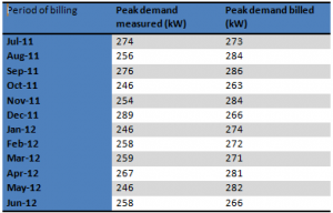
6‑2 billing average and low demands for 12 months period

Estimated Energy and Cost Savings
A net reduction of 28 kW has been estimated for electrical demand energy

Implementation Cost and Payback (Estimated)
The estimated cost for the implementation of this ECO is $50,000.
The ECO can be implemented by
- Contacting the local utility for the installation of new meter
- Confirm the capability of the SCADA system
- Training of the staff
Plant Impact
The plant staffing will not be affected by the implementation of this ECO.
ECO 4 – improvement of the water pumping system
Recommendation
Conversion of the froth spray system is recommended for the removal of the floatables to the water pumping system.
Background
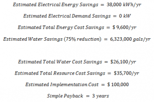
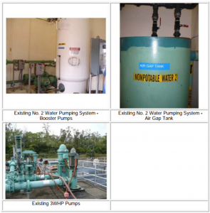
The water pumping system of No.2 is used for the odour scrubbers of mist type. The pump seal water system and froth sprays are also attached with this pump system. Water consumption is about 9.4 million gallons which uses about 8.7 million gallons/ year froth spray. The recommendation will stop froth spray from clogging. The booster pump works for 2 minutes with the operational profile of 50percent/year. Based on motor efficiency the electric load is 11.71 kWh. By using booster pumps the total electrical consumption is about 51,290 kWh/ year (estimated).
Energy and Cost Savings (Estimated)
The new operating time for water pump is 2 minutes and 6 minutes on and off respectively. This estimated time will reduce the energy of about 38,000 kWh/ year. Net water reduction will be 6323000 gallons/year.
Cost and Payback Implementation
The total preliminary estimated cost to implement this ECO is $100,000 and payback period is 2.8.
The ECO can be implemented as
- Integration of froth spray with No. 3 Water Pumping system
- Installation of new duplex basket strainer
- Retrofitting of froth spray nozzles
- Reduction of operating pressures
Plant Impact
The plant staffing will not be affected by the implementation of this ECO.
ECO 5 – the substitution of the lower efficiency motors with high efficiency motor
Recommendation
Installing new high efficiency motors is recommended.
Background
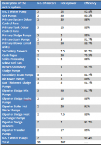
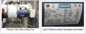
There are more than 170 motors on the site.
6.5‑1Equipment upgraded list
Energy and Cost Savings (Estimated)
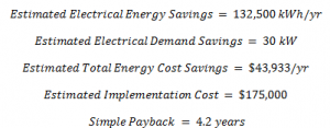
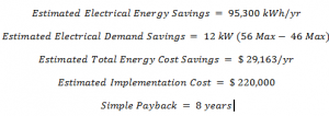
By replacing all motors with high efficiency motors the estimated electrical demand energy savings are

Cost and Payback Implementation (Estimated)
The total preliminary estimated cost to implement this ECO is $175,000.
The ECO can be implemented as
- Confirming operating hours, efficiency and equipment size
- Evaluating rpms, horsepower and loading
- Motor performance evaluations
Plant Impact
Implementation of this ECO is not anticipated to impact plant staffing or operating
Requirements
ECO 6 – improving water pumping system
Recommendation
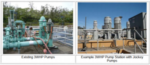
The pressure based system is recommended to be replaced by water pumping system.
Background
The water pumps are two in numbers with 40 hp power and rated as 540 gpm @ 175 feet of head
Energy and Cost Savings (Estimated)
Based on the plant discussions the following energy and flow projections
6.5‑2 current operation

6.5‑3 proposed operation


Cost and Payback Implementation (Estimated)
Total cost is estimated which is $180,000.
The ECO can be implemented by
- Installing Install VFD’s
- Installing new jockey pumps
- Complete the operation by the addition of the jockey pump through pressure controller
Breakdown of energy conservation measures and required O&M
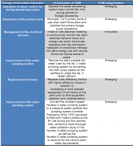
Life cycle cost analysis
The costs of the ECMs can be examined and weighed by lifecycle cost analysis over the life span of the facility. Considering the cost reduction and payback period, the replacement of motors is seemed to be a most effective investment in its whole life cycle. Considering the cycle costing, the cheapest investment is not a most favourable option but the justification is needed at all points of its operation. In this case we have selected the motor replacement as a most effective investment because of its low initial cost including low purchasing, acquisition and installation costs. The running costs of the equipment are low than the other facilities under consideration. The facility requires less maintenance and repair costs during its operation. The replacement cost is lower as it will include the payment of the existing unit. The residual values of the facility are high which include salvage, resale, disposal or other values. The facility has low finance charges with lower interest payments for loans. The investment has high monetary benefits along with lower investment costs. Life cycle analysis of the retrofit will save energy and thus money with the safety of employees. The basic purpose of the life cycle analysis of a facility is to make people healthier, productive, and happier. Altruistic factors including environmental and societal are justified in terms of lower electricity consumption, lower noise generation and higher efficiency.
Summary
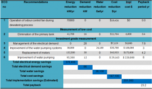
A site energy assessment of the Hilo waste water treatment plant facility has been performed in this report. The location of the facility is about 150 Kekawnoa Place in Hilo city of Hawaii. A valuable energy audit has been performed for its electricity and water assets and recommendations have been presented to save energy as much as possible. Following table shows the summary of the energy saving opportunities and presents various lesser energy consumption alternatives.
6.5‑4 summary of ECO
References
- Asian productivity organization (2008) Working Manual on Energy Auditing [Available online] <http://www.apo-tokyo.org/publications/files/gp-13-wm_ea.pdf> Retrieved 9th March 2013
- Carlos R. (2010) Energy Audits 101, Inspection Services Inc
- Christopher B. (2010) A GUIDEBOOK for PERFORMING WALK-THROUGH ENERGY AUDITs of INDUSTRIAL FACILITIES [Available online] <http://www.oregon.gov/ENERGY/cons/industry/docs/auditguide.pdf> Retrieved 9th March, 2013
- DAMODARAN C. THIRUMOORTHY N. PARTHASARATHY P. (2012) ENERGY AUDIT IN SUGAR INDUSTRY A PASSPORT TO PROSPERITY [Available online] <http://www.avantgarde-india.com/techpapers/Energy%20Audit%20in%20Sugar%20Industry.pdf> Retrieved 9th March 2013
- Dora Beck, P.E. (2009) BIG ISLAND’S BIG ISLAND’S WASTEWATER COLLECTION SYSTEM [Available online] <http://hwea.org/conference/2009CollectionSystemsPresentations/Session12C-DoraBeck.pdf> Retrieved 9th March 2013
- Hilo systems (2011) Annual Water Quality Report [Available online] <http://www.hawaiidws.org/7%20the%20water/ccr/2011/CCR%20S%20Hilo%20Hilo%202011%20lo.pdf> Retrieved 9th March, 2013
- Howells M. (2006) Targeting of industrial energy audits for DSM planning, Journal of Energy in Southern Africa, Vol 17 No 1. Energy Research Centre, University of Cape Town
- HELCO (2012) DRAFT REQUEST FOR PROPOSALS FOR RENEWABLE GEOTHERMAL DISPATCHABLE ENERGY AND FIRM CAPACITY RESOURCES ISLAND OF HAWAII, Appendix B – Bidder’s Response Package Hawaii Electric Light Company, Inc
- Intended Use Plan (2012) State of Hawaii Water Pollution Control Revolving Fund also known as the Clean Water State Revolving Fund (CWSRF) [Available online] <http://hawaii.gov/health/environmental/water/wastewater/pdf/iup-sfy13.pdf> Retrieved 9th March, 2013
- Jeremiah J., Leistra D. Jules O. Mason S. (2012) Hawaii County Baseline Energy Analysis, Yale University Environmental Engineering Program, Sponsored by the Kohala Center, Kamuela, Hawaii
- Victor D'Amato, (2012) the Importance of a Distributed Wastewater Management Architecture in Comprehensive Energy Analyses and Planning [Available online] <http://www.watereuse.org/sites/default/files/u3/D'Amato%2520WateReuse%25208-15-11%5B1%5D.pdf> Retrieved 9th March 2013
Get 3+ Free Dissertation Topics within 24 hours?


