
Limit State Design of Structures
February 1, 2021
Directional Drilling Technology
February 1, 2021
Part 1; Vector Algebra Analysis
From the given Values of the following drawing, AB = 75 mm, BC = 200 mm and CD = 150 mm
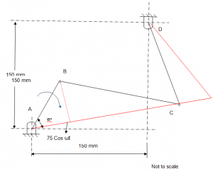
Assuming that the crank AB is at the furthest at Θo = t, with displacement of AB + BC = 275mm. Taking this as the reference point, the Position Vector Equation can be derived as;
(Eq-1)
From this equation-1, the displacement Vector diagram can be presented as;
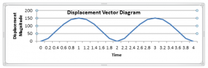
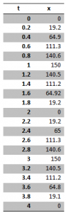
Calculated Values of displacement against Time are;
The equation-1 is differentiated to obtain the Velocity vector equation;
(Eq-2)
= (Eq-2)
From this equation-2, the Velocity diagram can be presented as;
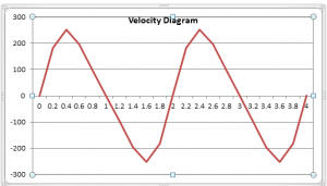
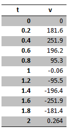
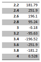
Calculated Values of velocity against Time;
The acceleration vector equation is obtained by differentiating Eq-2, which gives;
(Eq-3)
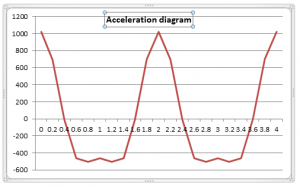
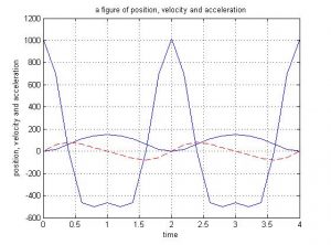
From this equation-3, the acceleration diagram can be presented as;
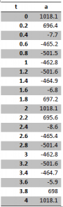
Calculated Values of acceleration against Time;
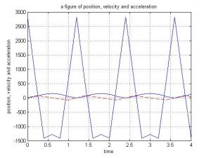
Summary of Results, performed with N = 30 (number of revolutions per minute)
Summary of Results, performed with N = 50 (number of revolutions per minute)


Part 3; Discussion
Mechanical transformations in a machine are produced by a certain mechanism and the transformation caused can be one of the following types:
- Conversion from liner to angular motion
- Conversion from angular to linear motion
- Conversion from one angular motion to another angular motion
- Conversion from force into torque
- Conversion from one torque to another torque
- Conversion from one force to another force
- Conversion from one speed to another speed
Example of such mechanism can be found in assembly of a crank connecting with rods and piston. Tuning of the crank produces an angular movement that is transformed into a linear motion, as shown in the drawing below;
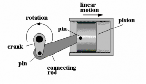
As shown in the figure above, the motion of the crank is transformed into the piston force. At any given time, the motion different parts of this mechanism have a displacement, change in displacement i.e. velocity and acceleration. The acceleration produced also increases also increases the inertia forces and hence adds stress forces into the stress that’s has been produced through the power transmission.
The example studied in this coursework, it was found that in mechanisms, the various parts of the assembly can be called the links that the mechanism are a product of series of four links. With forced movement of the input links, also may referred as crank, the output link is mobilized in a backward and/or forward movements.
The input is fed in by means of a motor working at a constant speed, which results in back forth movement of the rocking arm and vice versa for the head (moving back and forth). The movement of the heat can be made in forwards mainly through lengths of different parts but the return stroke is rapid at constant cutting speed.
It should be noted that the motion produced is a simple harmonic motion. The different parts of the mechanism, at any time have a certain acceleration, displacement and velocity. The inertia that results from acceleration exerts stress on the parts in addition to the stress caused by the diffusion of power. For an instance, the rod connected to the internal combustion engine. The mechanism is likely to be interrupted if the slider and the pin are not able to slide in perfectly
Displacement;
Almost every part of the mechanism has displacements. The displacement can be given as;
Displacement (x) = R sin (ωt)
Where, R is the radius, ω is angular velocity and t is the time of rotation.
Velocity
Same is the displacement, every mechanism has velocity. The velocity i.e the rate of change of displacement can be given as;
V = dx /dt = ωR cos (ωt)
Where, X is the displacement, R is the radius, ω is angular velocity and t is the time of rotation.
Acceleration
Same as velocity, every part of the mechanism has acceleration, which is the rate of change of velocity. Acceleration can be given as;
Acceleration (a) = dv/dt = ω2R sin (wt)
Where, R is the radius, ω is angular velocity and t is the time of rotation.
Analyses
The output values of displacement, velocity and acceleration can be calculated for any time moment and/or for any angle. These values could then be used to find out the force required (inertia force) to attain these values, such for velocity and accelerations. The maximum calculated values are mostly used for designing purposes. There are other mechanisms which can be mathematically analyzed, however these more difficult to analyze and require various software simulations.
In this course work, the equation for the displacement was derived in terms of angular speed and time of rotation. This obtained equation was differentiated to get the equation for the vector velocity, and then differentiated again (second time) to obtain the acceleration vector equation. A graphical method is then used to show the results obtained from these equations
The input is fed in by means of a motor working at a constant speed, which results in back forth movement of the rocking arm and vice versa for the head (moving back and forth). The movement of the heat can be made in forwards mainly through lengths of different parts but the return stroke is rapid at constant cutting speed.
It should be noted that the motion produced is a simple harmonic motion. The different parts of the mechanism, at any time have a certain acceleration, displacement and velocity. The inertia that results from acceleration exerts stress on the parts in addition to the stress caused by the diffusion of power. For an instance, the rod connected to the internal combustion engine. The mechanism is likely to be interrupted if the slider and the pin are not able to slide in perfectly.
Velocity Diagrams
The velocity diagrams are required to be developed very precisely and to an appropriate scale. It is recommended to use compass, triangles, drawing boards, protractor to be able to perform this task. One must also have the required drawing skills to produce velocity diagrams successfully.
Absolute Velocity
When a velocity is measured from a fixed point, it is called the absolute velocity. The fixed point can be anything ranging from the ground to any static object attached to the ground. Relative velocity, on the other hand, can be termed as the velocity of a point that is relative to an object or a point that may not be fixed.
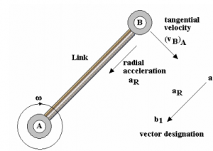
Tangential Velocity
Consider an example of a link X Y attached to Z and revolving about Z at an angular velocity ω. The velocity of point Y is always tangential or perpendicular to the link because it is moving is a circular motion about the point Z. Traditionally, the tangential velocity is given as (VY)X, which effectively means that the velocity of Y is relative to Z. However, this method may not be effective in certain conditions.
Acceleration Diagrams
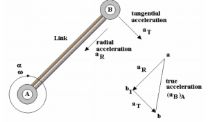
As discussed before, acceleration can give rise to inertia forces and therefore it is crucial to find out hr acceleration of links to determine the stress applied on various parts of the mechanism. Similar to velocity, the acceleration can be either absolute or tangential. However, we will be only discussing the radial and tangential acceleration in this section.
Radial or Centripetal acceleration
At radius R, a point revolving around a centre will have certain angular velocity ω and tangential velocity v. Although the point is never getting close to the centre, it is continuously accelerating towards it. The acceleration caused by the steady change in direction can be termed as the centripetal acceleration. The point that must be highlighted here is that the end of a revolving object or link will always have radial acceleration towards the centre. If this is true then,
The rules must be firmly followed because of the construction of the vector often creates confusion. Again, we can assume that the velocity of point B relative to point A is tangential and is given by
(VB)A
The acceleration of Y relative to A is the tangential acceleration since it is in a radial direction. Hence, the centripetal acceleration can be written as aR and is calculated by using the equation given below.
aR = ω x AB
or aR = V2/AB
The vector starts at a and ends at b1 even though the direction is towards the centre of revolving. It is extremely important to get this correct or the entire diagram will have to be redrawn.
Tangential acceleration
When the link possesses an angular acceleration α R/s2 then the resulting acceleration can be termed as the tangential acceleration. The concept of tangential acceleration can be explained by considering the example of a link AB with an angular acceleration about A.
The tangential and radial acceleration of point B will always be relative to point A.
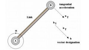
Taking the vector sum of the two accelerations will result in the real acceleration of point B relative to A. Use of an additional point b on the vector diagram can explain the idea more comprehensively.
As shown in the figure below, the acceleration of B, moving perpendicularly to the link, is circular. The true acceleration can be obtained using the relationship given below.
aT = α x AB. The vector ends at b and starts at b1. It should be noted that the letters a and b are just imaginary. Users can use choose any letters as long as they logically relate to each other.
The reason why it is important to determine the acceleration is to calculate the forces of inertia.
Forces of Inertia:
Inertia forces played their part in acceleration deceleration and they mainly depend on the Newton’s second law of motion.
From Newton’s second law of motion, we know that force is equal to the mass multiplied by the acceleration or F= Ma.
And therefore the Torque can be given by the equation below.
T = I x α
Where I is the moment of inertia and a is the angular acceleration
Coriolis Acceleration
Considering an example of a connection accelerating at α rad/s2 and angular velocity ω. If VR = dR/dt is the velocity if the sliding element moving away from the centre, then the vT = ωR is the tangential velocity of the link.
,
is the component of the velocity in the x direction Similarly, the velocity vR also has a component in a similar direction, which is vR cos θ


Appendices
>> t = 0:0.2:4;
>> w = 3.142;
>> v = 75*w*sin(w*t) + 2812.5*w*sin(2*w*t)./sqrt(40000 - 5625*sin(w*t).^2);
x = Columns 1 through 9
0 19.2474 64.9889 111.3436 140.6051 150.0000 140.5804 111.2927 64.9236
Columns 10 through 18
19.2003 0.0000 19.2945 65.0542 111.3945 140.6298 150.0000 140.5556 111.2418
Columns 19 through 21
64.8582 19.1533 0.0001
>> t = Columns 1 through 9
0 0.2000 0.4000 0.6000 0.8000 1.0000 1.2000 1.4000 1.6000
Columns 10 through 18
1.8000 2.0000 2.2000 2.4000 2.6000 2.8000 3.0000 3.2000 3.4000
Columns 19 through 21
3.6000 3.8000 4.0000
>> v =
Columns 1 through 10
0 181.6111 251.9151 196.2813 95.3782 -0.0600 -95.5082 -196.4019 -251.9170 -181.4304
Columns 11 through 20
0.2640 181.7915 251.9130 196.1606 95.2481 -0.1800 -95.6383 -196.5224 -251.9186 -181.2495
Column 21
0.5280
>> a = 75*w^2.*cos(w*t) + 7910156*w^2.*sin(2*w*t).^2./(40000 - 5625*sin(w*t).^2).^1.5 + 5625*w^2.*cos(w*t).^2./sqrt(40000 - 5625*sin(w*t).^2) - 5625*w^2.*sin(w*t).^2./sqrt(40000 - 5625*sin(w*t).^2);
>> a = 1.0e+003 *
Columns 1 through 9
1.0181 0.6964 -0.0077 -0.4652 -0.5015 -0.4628 -0.5016 -0.4649 -0.0068
Columns 10 through 18
0.6972 1.0181 0.6956 -0.0086 -0.4654 -0.5014 -0.4628 -0.5016 -0.4647
Columns 19 through 21
-0.0059 0.6980 1.0181
References
- "J. Michael Jacob", 'Industrial Control Electronics', 'Application and Design', I.S.B.N: 0-13-4593065.
- "J. L. Martins de Carvalho", 'Dynamical Systems and Automatic Control', I.B.S.N: 0-13-221755-4.
- "Stanley M. Shinners," 'Modern Control System Theory And Application', I.S.B.N: 0-201-07059-6.
- "W. Bolton", 'Control Engineering, 'Second Edition', I.S.B.N: 0-582-32773-2.
- http://mechatronics.mech.northwestern.edu Date Accessed: 04/07/2013
- http://ctms.engin.umich.edu/CTMS/index.php?example=MotorSpeed§ion=SystemModeling
Get 3+ Free Dissertation Topics within 24 hours?