Dynamics and Control
February 1, 2021
Simulation of Vehicle Performances with Different Power Systems
February 1, 2021Chapter 1; Introduction
“The bottom of the oil barrel is now visible” a mind wobbling statement by Christopher Flavin emphasizing the dependence on fossil fuels that mankind has had over the last century and a half. According to a research, most fossil fuel reserves will be depleted within the next century. An alarming statistic for the spoon fed society of the 20th century. Scientists and research based personnel have been struggling to find answers regarding these problems and hence different techniques and tools have been invented and being used to make use of the limited resource that remain.
Directional Drilling can be simply defined as drilling towards the target using various tools and equipment. These oil reserves are usually located at some horizontal distance away of the well site or the drilling rig. Generally, wells are not drilled in straight line; if this was possible then drilling would have been an extremely easy task to perform. It should be noted that installation of pumps and completion of wells is very hard when using directional drilling techniques[1][2].
When two or more wells are required to be drilled from a single platform then well completion and pump selection must be performed simultaneously with directional drilling. Drilling of multiple wells from a single drill pad is occasionally required in geo thermal electrical generation reservoir.
Some other reasons why the well completion and selection of pump (s) must be done with directional drilling methods include:
- Intersecting a fault for enhance production
- Bypassing or sidetracking a junk that cannot be slipped through a hole
- Reducing the probability of fault movement shearing by drilling in straight line in proximity to a fault
Although different types of direction drilling been have been used for many years, it is only in the last decade this method has gained worldwide importance and recognition.
Aims of the Project
- To understand directional drilling, its background and the activities.
- Different methods of directional drilling
- Defining drilling operations and its complete process
- Research development under progress
- Parameters involved in this field
- Associated problems risks and safety aspects
- Calculation/designing performed
- Challenges in the new changing world
Background of Directional Drilling
The industrial boom in the 19th century had made it vital for technology to be redefined in such a way to cater to growing needs of the ever-growing society and thus fuel and petroleum needs hiked towards dangerous levels. Thus different methods paved their way into existence once the demand scales flourished and hence different drilling and extraction techniques came into being.
Although the techniques and attempts date back to early 19th century but the first well drilled was by Edwin Drake in 1859 in Venango County, near Titusville in Pennsylvania. According to Department of Environmental protection and the first well drilled off short was in 1887 near Summerlan, California but it wasn’t until 1947 that a large scaled fixed oil platform was built way beyond the shores inhabited by us. But these records state use of drilling machinery on large scale with the aim of finding oil reserves but drilling for other purposes like brine and other simplistic lucrative outcomes of digging holes in search of food, water and escape routes if need arises. Pre historically people started using simple handmade tools such as sticks and stones to use as digging tools. Still in China a custom has carried on that dates as far back as 600 B.C when holes were dig and drilled for brine.
It was until the start of the 19th century when mankind realized what lay beneath their feat and started to go underground to cater to the industrial revolution. Once this realization incepted the egoistic minds of mankind it was only a matter of time until new methods and techniques were invented according to new research results that showed that there was much more to oil reserves than that what meets the eye. Oil reserves were not just simple vertical wells but turned out to be a lot more than that. The oil industry has proved itself to be a multibillion dollar industry and hence has attracted many a thousand towards this lucrative search for more and more oil reserves[3].
It’s amazing how far this industry has come and much like bounty hunters, oil reserve searching personnel have wondered into deep water where they have found large amount of reserves after nearly depleting those of the shallow waters of Gulf. Drilling which basically symbolizes making a borehole into the ground and using piping to prevent collapsing of the borehole has taken many shapes and turns since its arrival. Even the first drilling mechanism used by Drake who is well known for unlocking the world of drilling, used a steam fired engine to automate the drilling machine and used piping to prevent boreholes collapse.
The techniques has hence been modified to gain speed in drilling which started at around 3 feet per second and has ever been increasing with modern technology. The Oil reserves were thought of as simple vertical wells in early stages and hence seemed easy to gain the maximum out of the reserves once the reserve was reached during the drilling mechanism. But recent surveys have suggested that the so called simple vertical wells are far from simple. It was believed that non vertical wells were a huge disadvantage. These surveys took place in late 1920’s to measure the deviation of wells and which turned out to be up to as high as 46 degrees with an average of 13 degrees deviation from the typical vertical position of wells.
The first controlled directional well was drilled successfully in 1930 to reach oil reserves off shore in California. Since then the directional drilling mechanism has come a long way to help modern scientists and researchers to make the most out of whatever reserves that remain and give them ample time to come up with alternate resources for energy consumption.
Chapter 2; Directional Drilling Applications
This chapter will mainly look at the objectives of directional drilling, how it is performed and what are the safety and operational requirements.
Directional drilling has had plenty of applications since it came into existence. Applications like sidetracking, finding multiple wells off shore, fault drilling, Salt Dome drilling, Shoreline drilling, horizontal drilling etc have been used since the last century. With careful planning, a lot of homework, skillful coordination, pre-project monitoring and surveys coupled with some amount of luck, directional drilling have the capability to be substantially efficient as far as energy consumption, cost and time are concerned.

Figure 1; Oil & Gas extraction facility (source: edited using MS paint)
Following are the categories under which various Directional Drilling applications are placed[1]:
♦ Side-tracking ♦ Fault Drilling ♦ Salt Dome Drilling ♦ Drilling Relief Wells ♦ Multiple Wells from offshore structures ♦ Controlling vehicle holes ♦ Shoreline Drilling ♦ Drilling of multilateral wells ♦ Drilling beneath inaccessible locations ♦ Horizontal drilling
Directional Drill Applications
In this section, we will be looking at the technical details as well as safety and operational requirements for all mentioned Directional Drilling applications.
Sidetracking from a Wellbore
Sidetracking from an available wellbore is perhaps one of the most popular directional drilling applications. A new hole is typically started at any point right over the available by deflecting the borehole. The sidetracking operation allows intersecting a producing formation at a desired position, bypassing a fish or an obstruction that has been lost in the bore hole, sidetracking an exploration well for exploring further details, moving away from a depleted part of the reservoir and drilling a horizontal path from the available well bore.

Figure 3: Side tracking from wellbore (source: edited using MS paint)
Multiple wells from a single drill site
Drilling multiple wells from offshore structures is the most commonly used directional drilling application in the world. Engineers perform various technical tasks to drill multiple directional wells from a fixed platform. A single directional well can give access to various reservoirs allowing targets to enter at specific angles, ensuring improved efficiency and extraction from an existing pool.
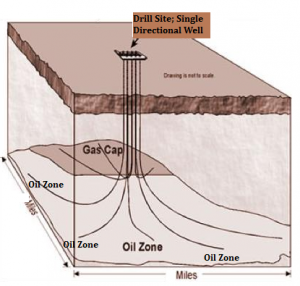
Figure 4; Example of accessing multiple wells through one central site (source: edited using MS paint)
Fault Drilling
Whenever there is a need to drill a vertical well, directional drilling is performed through a sharply inclined fault plane. Problems have been reported when attempts to drill through the fault casing shearing have been made.
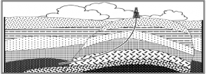
Figure 5: Fault Drilling (source: goggle e-book image)
Salt Dome Drilling
Another type of directional drilling application is the salt dome drilling which is usually performed when it is imperative to drilling nearby subsurface geological hurdle. Engineers design the drilling operation in a way that the well is drilled at only one side of the salt dome, thereby deflecting underneath and around to avoid the salt dome. This practice can help in dealing with problems such as flu loss to the formation, stuck piping and damage to the well. The figure below illustrates sale dome drilling application.
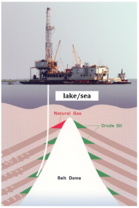
Figure 6: Sault/Dome drilling site (source: self edited using MS paint)
Drilling for Controlled vertical wells
Controlled vertical wells are drilled by using directional strategies to stay avoid going beyond the lease boundaries of a certain reservoir. Some drilling parameter may be altered and the bottom hole assembly may be changed to achieve this goal. In some cases, there may be a requirement to use a bent sub or a downhole motor.
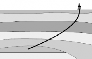
Figure 7: Controlled Vertical well (source: goggle e-book image)
Drilling beneath inaccessible locations
Sometimes it is required to access reservoirs directly underneath the man natural obstructions or man-made obstacles. Directional drilling technique must be employed to overcome to such problems.
Relief Wells drilling
Directional drilling is also employed to be able to kill blow outs. Relief wells are deviated in order to pass as close as possible to the unrestrained well. Heavy mud is added to the reservoir to tackle pressure and blowout challenges
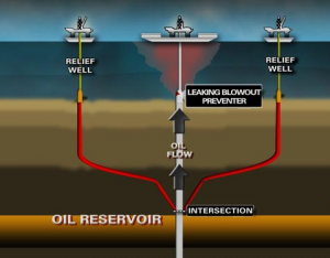
Figure 8: Relief well (source: goggle e-book image)
Shoreline drilling
Wells are drilled by using directional drilling techniques from a land rig in order to access the offshore reservoir which is also close to the land. Studies have shown that this method is an inexpensive way of accessing the producing formation.
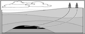
Figure 8: Shoreline drilling (source: goggle e-book image)
Horizontal drilling
When the aim is to improve the productivity of various formation, the use of directional and horizontal drilling becomes imperative. This technique is commonly used when the formations are thin layered and for fracture reservoirs. Advantages of horizontal drilling include improved penetration of producing formation, dramatic increase in productivity from the reservoirs, improved efficiency of oil recovery, enhanced drainage area and solution to water conning problems.
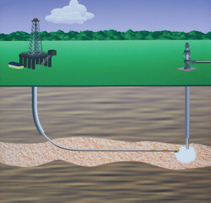
Figure 9: Horizontal drilling technique (source: goggle e-book image)
Drilling of multilateral wells
Directional drilling techniques are also applied to drill multilateral wells, which are created when two or more directional drill branches are created from the same platform. The first multilateral wells were drilled in Russia almost 60 years ago. Since then this technique has been used in various parts of the world including the United States, the UK, Japan and Middle East.
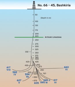
Figure 9: multilateral well (source: goggle e-book image)
Chapter 3; Offshore drilling platforms
An offshore platform or an oil platform can be defined as a large structure designed to drill wells to extract natural fuels such as oil and gas from underground reservoirs. An offshore platform also has the facility to store oil products until it can be transported to the refinery. Offshore platform are huge and sometimes they even contain the facility to house several employees. Depending on the design, the offshore platform may float on the surface, may be fixed to the floor of the ocean or may be built on an artificial island. Occasionally, subsea wells are also connected to an offshore facility through flow lines.
The first submerged oil well from platform was built in 1891 at the Grand Lake St. Marys in the United States. The first submerged well in salt waters was drilled five years later under the Santa Barbara Channel in the US. Since then offshore wells have been drilled across the world.
Directional drilling has contributed gradually towards reducing costs through drilling multiple wells from the same location. The platforms today are designed to perforate both shallow water and deep water low-level regions as deep water, where directional wells are drilled to obtain optimum use of radio drain the reservoir.
According to leading companies, the cost of drilling represents approximately 40% of the costs of discovery and development. Facts show that with the use of directional drilling wells, in offshore areas, the reduction in costs of an operating day is approximately $ 100,000 USD.
Fixed Platforms
Fixed platforms are perhaps the most widely employed class of offshore platforms. They are mainly built on steel legs or concrete or both, depending on the waters the wells are required to be drilled in. The steel or concrete legs are directly connected to the seabed to support production facilities, crew quarters and a deck for drilling rigs.
Compliant towers
They are made up of a pile foundation and slender flexible towers to support production operations, crew and conventional deck for drilling operation.
Semi submersible platform
This type of platforms is designed to be able to float whiling keeping the structure upright. Semi submersible platforms have pontoons and columns of adequate buoyancy to perform the task of floating on water. The semisubmersible floating facilities are composed of a cover which is mounted on vertical columns, which in turn are supported by pontoons. The semisubmersible rigs maintain their position by chains anchored to the seabed. The platforms can be converted semisubmersible drilling rigs and production platforms vice versa, provided that the appropriate adjustments are made, designed to avoid stability problems for the distribution of its weight. In this part of the hydrocarbon transport and storage in production systems are the only problems encountered by environmental conditions such as ballast water pollution and oil spills.
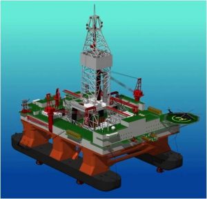
Figure 10: semi submersible platform (source: goggle e-book image)
TLP Technology steel structures are concrete or semi-submersible, but with the difference that are supported by steel pipe to a base located on the seabed[1]. This kind of platforms has a helmet and a cover positioned on a template and columns containing associated ballast tank pumps control. Technology platforms stretched legs (TLP) began with the development of offshore fields in the North Sea, which subsequently led to the development of the first platform TLWP (Tension Leg Welhead Plataform). The TIWP is a version of the TLP but with smaller dimensions and capacities, and it does not have enough space to place all the equipment required for the handling and transportation of hydrocarbons, in addition to limitations on the capacity of pumping and compression equipment. There are other platforms called micro TLP, which providers use in deep water when field development requires a small number of wells and short operating time, in order to reduce investment.
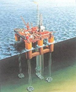
Figure 11: semi submersible platform (source: goggle e-book image)
SPAR platform technology
This technology combined simple geometry application platform wells, i.e. which has a direct access to the wells from the platform. The original cylindrical type SPAR experienced vibrations and shocks caused by current hurricane that's where the wave breaks or current, so it has remained on the platform and made it more stable because it has its metacentre right below. To overcome platform vibration and reduce the weight of steel spar, spar structure is designed to withstand weight and balance riser combining Archimedes' Principle and the geometry of anchor. This system is best suited when the site contains large volumes of hydrocarbons.
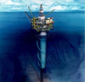
Figure 12: SPAR platform (source: goggle e-book image)
Boats Borers (drillship)
These vessels are simple system adapted to be used as drilling medium; these are known for their high storage capacity, high mobility but low drilling capacity. These vessels try to maintain stability by stabilizing tanks and other methods. They remain stabilized over the well through the use of dynamic positioning systems.
Such units with respect to the semi-submersible units have a greater storage capacity drilling fluid, fuel, and water.
The ability to maneuver these boats is up to 10,000 feet deep and 35,000 feet of strata to be drilled, also can accommodate up to 200 people.
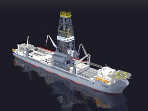
Figure 13: Drill ship (source: goggle e-book image)
Jack-Up Platforms
These types of platforms are widely used worldwide for the purpose of drilling in shallow water of more than 500 feet deep.
Structurally, these units consist of a flat base with three or more support legs, accommodated by recesses at the edge of the base. These legs are formed by slots which have inserted teeth, serving to lower or raise the flat base with a hydraulic lifting system or an electric system. After completing the drilling process, the base is lowered until it floats freely, and it proceeds to lift the legs for moving the unit to another location. The inserted teeth are responsible for allowing downward or upward movement of the same.
These mobile platforms can be transported by tugs or self-propelled. It is intended for exploratory drilling on the continental shelf.
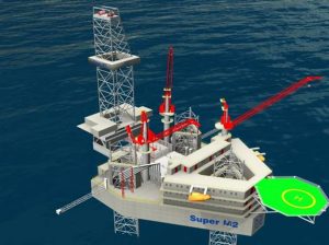
Figure 14: Jack up platform (source: http://www.cimc.com/)
Concrete gravity based structures
These are heavy concrete structures which are fixed in place on the seabed as a result of their weight without the need for piles. Some major advantages for concrete GBS are the high structural strength, possibility of hydrocarbon storage within the structure and that reinforced concrete, which is not susceptible to degradation of material properties due to extremely low temperatures.
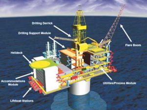
Figure 15: Gravity based concentrate platform (source: goggle e-book image)
Chapter 4; Directional Drilling Literature Review, Research and Design
It is not possible to achieve maximum efficiency without carefully planning and outlining the direction wells drilling with engineering and financial prospective. The cost of the drilling directional wells can be reduced significantly by planning in advance. Success of this task depends on designing various programmes for the well.
Usually a company or an individual is responsible for managing programmes such as the drill string design, casing programme, bit programme and the mud programme. The figure below shows how important directional well planning is to successful completion of directional drilling operation. Drilling depth reading typically begins from Drilling Floor, Rotary Table and Kelly Bushing. When the well is required to be drilled vertically, the Kick Off Point is determined to indicate the starting position[1]. End of the build section is usually shown by the End of Build/Curve point, which is usually written with the abbreviation of EOC or EOB. The Hold or Tangent section is the point where the inclination is invariable. Reference coordinates and systems will also be discussed briefly in this section.
The coordinates and applied reference methods
Apart from the inertial navigation systems, all survey systems gauge azimuth and inclination at a specified measured depth, denoted by MD. The measurements taken are usually linked to fixed referencing system to be able to determine the path of the wellbore. Following are the three reference systems:
Depth References:
This reference system is typically based on two kinds of depth along the wellbore path. These two depths are the True Vertical Depth and Measured Depth. Measured depth is defined as the distance between the survey point and the surface reference point, measured along the course of a directional well. Mud loggers’ depth counter, pipe tally and wireline depth counter may be used for accurate measurement of measured depth. True vertical depth on the other hand is the vertical distance between a point on the borehole path and the depth reference level.
Inclination References:
The inclination of the wellbore is described as the angle between the wellbore axis at a specified position and the vertical axis. Vertical reference can be obtained from the direction of the local gravity.
Azimuth Reference Systems
This reference system can be further divided into three categories including the Grid North, Magnetic North and True Geographic North.
Grid North:Even though direction drilling processes are performed in curved systems, the earth surface is considered to be flat when determining horizontal plane coordinates. Since it is impossible to represent a curved system as flat, various projection systems must be employed to be able to get accurate readings.
True Geographic North: It is the direction of the geographic North Pole and direction on the maps are shown using the meridians of longitude.
Magnetic North: It is the hole direction with reference to magnetic north. Coordinates are referenced to Grid North and True North.
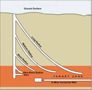
Figure 16: Defining radius curves (source: goggle e-book image)
Table 1; Directional well classification
Radius Type | Radius (Feet) | Achievable Lateral Length (Feet) | Method |
| Zero | 0.0 | 10.0 | Hydraulic-jet using telescopic probe |
| Ultra-Short | 0.50 – 5.0 | 200.0 | Hydraulic-jet using Coiled tubing |
| Short | 35.0 – 45.0 | 1500.0 | A Curved drilling process, using flexible drilling pipes. |
| Medium | 300.0 – 500.0 | 1500.0 | Steerable mud-motor using compressive drilling pipe. Other drilling technologies may also be used |
| Long | 1800.0 – 2800.0 | 1500.0 + | Equipment of Conventional/regular directional drilling may be used, a long curve-length of nearly 2850 to 4450 (ft) is required be drilled horizontal before horizontal is achieved |
| In-Mine | N/A | 5000.0 | Under-ground drill rigs using steerable-motors and positioning system (s) to gain long and inseam bore-holes |
Directional Surveys:
Direction surveys are required to be conducted at regular intervals to be able to identify the bottom hole position with respect to the surface point. A number of survey calculation methods are used globally. All surveys must be converted to True Vertical planes, North South and East West, which are then put down on vertical and horizontal planes. Drilling process can be monitored and adjusted using the plotted survey data[1].
As discussed before, there are numerous survey used in the oil and gas world. However, we will be discussing only the most popular and important ones in this section. Average Angle, Radius of Curvature, tangential and Minimum Curvature Methods will be conversed brief under this chapter.
Survey calculation -Tangential
Not too long ago, tangential survey calculation method was the most widely used in the world. The fact is extremely easy to use and calculations are easy to perform made it an obvious choice for geologists. However, it should be noted that the readings for wellbore position may not be as accurate when compared to other similar techniques. The use of tangential method is not recommended at all since it gives a significant wellbore position error. The figure given below illustrates how this method assumes the path of the well bore to be a straight line between two survey points.
Survey calculation - Averaged Angle
The averaged angle method is far more accurate than the tangential method mainly because it defines the straight lines by taking an average of the inclination and azimuth at both survey locations. This straight line is also assumed to be intersecting both the lower and upper survey locations. The use of average angle method is highly recommended if a computer or programming software is unavailable. The figure below exemplifies this technique.
Survey calculation-Radius of curvature
Radius of curvature method is perhaps the most recognized and accurate survey method as this takes into account various factors such as the smooth curve between the lower and upper study points. Figure below shows this method.
Survey calculation- Minimum Curvature
This method is quite similar to the Radius of Curvature. The radio factor must be determined using the curvature of the wellbore and then multiplied by the same equations as for RCM. Furthermore, this method can accurately give the wellbore location. Numerous companies across the world use this method for directional drilling survey calculations.
MWD and Challenges in the new world
It is vital to be familiar with the work practices and new technologies that are proposed for ensure improved drilling and planning of wells in the future. Following technologies can improve the processes of well planning and drilling.
- MWD – Measurement While Drilling
- MAP Method
- Multi Disciplinary Approach
- Gyro MED Technology
- Wired Drillpipe WDP Technology
Only MWD and MAP Methods will be discussed briefly in this section.
MWD – Measurement While Drilling
MWD is a method is adopted by the Oil and Gas Industry to streamline the measurement data at different parts during the drilling process. While the well is drilled, measurement data is transmitted to the control room through the MWD tools. These tools are installed along with the bottom hole assemble close to the drill-bit, and are contained in the drill-collar or in a thick wall. This method is equipped to take measurements and provide data such as drill direction (azimuth), gamma rays information, bit direction/tool-face, pressure of borehole, vibration and shock measurements, temperature and many more. The rotary steering tools can also be operated using this system of communication[2].
Through the use of MWD tools, the directional surveys are obtained in real time. The system functions through the use of accelerometer and magnetometer to calculate azimuth and inclination. This real time survey analyses helps the user to identify the direction of the drilling process and the steering effects. The data is transmitted through the use mud pulse telemetry method via pressure variations in the drilling mud. This technology is operated in forms of positive/negative pulse and continues wave.

Figure 17: MWD Tools (source: goggle e-book image)
MAP- A New Wellbore Position Calculation Method
The map method involves identify the position of the wellbore using accurate survey methods and tool and each and every section of the well. It will not be wrong to say that this has become an reliable and commonly used practice for determining the wellbore location in the drilling industry. Each section of a modern well bore is surveyed multiple times using magnetic, inertial and gyroscopic instruments to identity the correct position of the wellbore.
The MAP or the Most Accurate Position method was proposed by C.R> Chia e al. which allows the user to combine several wellbore surveys into a single combination to determine a more accurate well position.
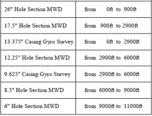
Example Survey programme
Figure 18; Schematic plan view of an example survey program for planned directional well
The main advantage of Map is the fact the level of uncertainty can be reduced significantly by relying on many surveys. Furthermore, it can drill smaller targets at larger distance very accurately.
Cooperation between Drilling and Geosciences
Cooperation between drilling and geosciences should be given a lot of important to ensure better quality of well planning and to minimize the operation risks involved. The partnership has played a key role in improving the work quality of production and exploration companies that now look for new technologies, cost effective and multi disciplinary and efficient work flow. Roxar has developed a new software package to improve the process of well planning by using three dimensional visualization tools[1].
Safety aspects
As discussed in the previous chapter, drilling of oil and gas plays a key role towards successful oil and gas industries and therefore it is absolutely vital to use industry best practices to ensure maximum efficiency and adequate safety.
Safety of employees is the first concern as they come across various unforeseen hazards while working with complex drilling techniques. Protection of environment is as important as any other aspect. Almost all companies have incorporated the concept of green technology in their operations. The third and another important aspect is the safety of related equipment and economic viability so the investors can earn profits on enormous amounts of investments. There should be sufficient information for the employees including engineers and driller to perform various drilling operations safely[2].
Considering the challenges mentioned above it is important to provide intensive training to employees and ensure the availability of detailed seismic and geological information[3].
As mentioned earlier, hydrocarbons must be prevented from getting to the surface during the drilling operation. The three main factors that can control this problem are:
- Drilling mud
- Blowout preventers
- Cementing
Only drilling mud and blowout preventers will be discussed in detail in this section.
Choosing the right drilling fluid can reduce the safety risks considerably. Mud can perform many functions that are considered to be essential for safe penetration. Following are the safety aspects of mud:
- It prevents hydrocarbons from entering the well
- Ensure the hole in clean and gives information about the formation
- Provides support to the walls of well
- Prevent rocks from collapsing
- Provides support to the bit, cooling and lubrication
- Helps is reducing the overall weight of drill string to ensure smooth rotation
- Reduce damage to the formation and the environment
- Following are the challenges that can be encountered when during drilling operations:
- Uncontrolled shallow gas formation can result in blow out
- Uncontrolled hydrocarbon in the well can result in blow out
- Drilling fluid can be lost if there is unconsolidated formation during drilling
- Gas escaping from well into the mud system
Blowout Preventers
Blowout preventers are used to control the formation of fluid flow in the well as uncontrolled fluid flow can result in blow out. Engineering companies are required to use sufficient prevention systems to avoid catastrophes that can lead to losses of lives, environment and property[4].
With technology improving with every passing day, blow out prevention systems have become more efficient and reliable than before. Following are some of the mostly commonly used prevention systems used now-a-days:
The well control system: This type of system used to keep circulating the formation fluid by maintaining a perfect balance between pressure.
The diverter system: this is used to keep un controlled formation fluid away from the staff and expensive equipment such as the drilling rig. There are four main components of diverter systems, which are: Annular preventer, the diverter line or the vent, valves and controls and the conductor casing.
Chapter 5; The Cost of Drilling – Estimation Models
Much research has been conducted to produce the models that could be applied to estimate the cost of the drilling for a project. However due the complexity involved in the drilling processes, such as drilling rates and tools to be used, much difficulty has been observed in producing simple models and also in their applications. One of the methods that has gained popularity in the recent past is the Joint Association Survey (JAS) and the Mechanical Risk Index (MRI). In an effort further develop and enhance the engineering efficiency, the method of Mechanical Specific Energy has also been developed[5].
The engineering cost is best estimated through categorizing the the completed drilling process into a sub divisions in the form of; site identification, rig placements and transport, drill and engineering operations, evaluation, placements, well-completion and trouble shooting. Cost estimations models are then applied to each category with given variables and expected performances. Further divisions in each category can help minor cost identification which eventually helps in highlighting the key cost drivers in both the variable and fixed costs columns.
Joint Association Survey (JAS)
The official JAS or Joint Association Survey was first conducted in the United States around six decades ago. Since the JAS on drilling costs is performed jointly by the Petroleum Association of American, Mid Continent Oil and Gas Association and the American Petroleum Institute, the collected data and results are published every year. The aim of this survey to ensure provision of data related to the cost of drilling, developments, oil production and findings in the United States. Perhaps, the Join Association Survey is the only programme that provides onshore and offshore drilling cost data for each and every state in the country. It will not be wrong to say that it is a primary source of information for the government and academic industry[6].
Joint Association Survey is designed to be quite accurate. The survey methods is very simple, involving questionnaires that are sent to operators in the drilling industry so the cost information for well completions performed during the year can be verified. All wells that are not completed in the year of survey are excluded from the report. The response rate from operators is also as high as 60 percent, which confirms the accuracy of information provided.
Estimation
The cost estimation method for JAS has changed over the years to ensure maximum efficiency. In 1950s and 1960s, wells were used to be classified depending on the drilling conditions, economic factors and well geological structure. In the second phase from 1966-1977, the cost of drilling per foot was calculated according to location, depth and well. The relationship given below was used to compute the cost of drilling.
Where TD represents the total depth of the well and Z is the cost per foot
In the third phase of evolution, the cost per foot of drilling for each sample area was computed using stepwise linear regression. Three depth variables including depth, depth squared and inverted depth as well as other dummy variables for well class, completion type and well type was employed to reach a functional form given below
From 1995 till today, wellbore data is aggregated into sixteen geo-graphic areas. For each region, a non liner and two factor regression model has been created, which is given below.
lnY
Mechanical Risk Index
This method was first used by engineers from Conoco Philips that we required to perform the task of comparing offshore drilling data for various wells in the Gulf of Mexico. Taking into account empirical analysis of well and other factors such as measured depth, kick out point and water depth, engineers developed the Mechanical Risk Index to compare operation. The MRI was modified and improved by Dodson in the mid 1990’s by using key drilling factors. The four component factors and the key drilling parameters are used to define MRI. The component factors incorporate six primary variables whereas the key drilling factors is the combination of fourteen qualitative gauges[7].
Component factors
As discussed before, the primary variables of the MRI are used to formulate the four component factors, given below.
Definition/Estimation
The MRI can be computed using the component factors as well the drilling factor with the help of the formula given below. Whenever there is a need to compare drilling performance of more than two wells, the MRI method is used. Mechanical Risk Index is also correlated to drilling costs.
Mechanical Specific Energy
Teal and Simon combined to introduce the concept of Mechanical Specific Energy to the World. The concept mainly involves the level or amount of energy needed to destroy a tock or rocks[8]. It can also be used to assess post well performance analysis, as a real time tool to improve the penetration rate, evaluate the drilling efficiency and get a more objective evaluation. It should be noted that the MSE is not used to estimate cost of complexity rather a method to optimize ROP for improve drilling and technical limitations. For a given volume of rock, the MSE can be calculated using the relationships given below
Where DIA is the diameter of drillbit and Tor is the torque.
Chapter 6; Applied Engineering Drilling methods
The primary step in the design of directional drilling is to figuring out the trajectory or the well-bore path to reach/intersect a given target[9]. The primary design normally proposes various path types that bee drilled viably. The following gives the three paths of the drilling process to reach the target
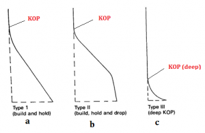
Figure 19: defining drilling types (source: edited through MS Paint)
- Type I — Build and Hold: This is the most common sketch/path for a directional well[1]. This works by drilling the hole vertically down to the Kick Off Point (KOP), regularly used for drilling deeper wells with large horizontal departures, with a normal inclination between 15deg to 55deg[2].
- Type II — Build, Hold and Drop (“S” ): This type is similar to type I down the End of Curve (EOC), where the curve reduces, and sometimes turn into vertical line. At that point, extra torque can be expected, due to extra bend The Type 2 is most appropriate to wells exposing multiple production zones.
- Type III — Continuous Build:Type III is used on specific circumstances and trajectories, as sidetracking or salt dome drilling, in this case the KOP is much deeper than in the first two types
The following sections explains how each of these types are designed and calculated with reference to the trajectory[3]
Type I: Build and Hold Trajectory Plan (a)
In order to design/plan this trajectory, the following Information is required:
- Surface coordinates
- Target coordinates
- True vertical depth of target (TVD)
- True vertical depth to Kick off point (KOP)
- Build-up rate
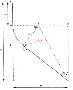
Figure 19; TypeI1 (a) (source: edited through MS Paint)
Target coordinates and depths are carefully chosen by the geologist and in the other hand the choice of KOP and Build-up rate, is assessed and selected by the site engineering team.
From the figure above, the horizontal displacement of the target (Ht) can be calculated by the following equation 1:
Eq. 1.1 Ht=((Nt - Na)2 + (Et – Ea)2)1/2
Where:
Nt: North of the target
Et: East of the target
Na: North of slot
Ea: East of slot
The proposed direction can also be considered from the horizontal plan, with the following formula:
Eq. 1.2 β= tan-1 (
Having the horizontal displacement calculated by Ht, the point C is the end of the curve, when the maximum inclination is reached. The next step is to calculate the maximum angle of inclination, when Build-up rate = ϕ per 100 ft using the following calculations:
Radius of curvature (R)
Eq. 1.3 R=
Maximum angle of inclination (α),
α=x+y
Eq.1.4 x= tan-1
+
y= sin-1( )
The following equation can also be derived for/at the point C:
Eq. 1.5 True vertical depth = Vc = Vb + R sin α
Eq.1.6 Horizontal displacement = Hc = R (1-cos α)
Eq.1.7 Measured depth = MDc = MDb +100
Also the measured depth at T can be given as:
Eq. 1.8 Measured depth= MDt = MDc +
Type II: Build, Hold and Drop Trajectory Plan (b)
In order to design/plan this trajectory, the following Information is required:
- Surface coordinates
- Target coordinates
- True vertical depth of target (TVD)
- True vertical depth to Kick off point (KOP)
- Build-up rate
- Rate of drop-off
- Required TVD at end of drop-off
- Final angle of inclination through target
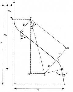
Figure 20: Type II (b) (source: edited through MS Paint)
From the figure above, the distances Vb, Ve, and Vt are given through surveying analyses, and horizontal displacement Ht can be calculated using the same formulas as we used in Type I. The radius of curvature R1 can be solved by calculating build-up rate (ϕ1), in the other hand R2 can be calculated from drop-off rate (ϕ2). We also have to find α1, since CD is parallel with CD, and OP is vertical.
Angle α1=x+y
Where,
Eq. 2.1 tan x = and tan y =
Eq. 2.2 OQ = Ht – R1 – R2 – (Vt –Ve) α2
Eq. 2.3 OP = Ve –Vb + R2 α2
Eq. 2.4 QS = R1 + R2
Eq. 2.5 PS = (PQ2 – QS2)1/2 where, PQ = (OP2 + OQ2)1/2
Once the calculation are performed to obtain the values OQ, OP, QS and PS, angles x and y can also be calculated. Points C, D, E, and T can be calculated with the following equations.
At point C
Eq. 2.6 Vc = Vb + R1 α1
Eq. 2.7 Hc = R1 – R1 α1
Eq. 2.8 MDc = MDb +
At point D
Eq. 2.9 Vd = Vc + PS cos α1
Eq. 2.10 Hd = Hc + PS sin α1
Eq. 2.11 MDd = MDc + PS
At point E
Ve (Known)
Eq. 2.12 He = Hd + R2 (cos α2 - cos α1)
Eq. 2.13 MDe = MDd +
At point T
Eq. 2.14 MDt = MDe +
Type III: Continues build Plan (c)
In order to design/plan this trajectory, the following Information is required:
- Surface coordinates
- Target coordinates
- True vertical depth to Kick off point (KOP)
- Build-up rate
- Maximum angle of inclination
Figure 21; Type III (c) (source: edited through MS Paint)
Having known Vt, Ht, and Vb from fig above, it can be derived that:
= tan-1( )
In order to find the final inclination, the following equation can be used:
Eq. 3.1 α2 = 2 tan-1( )
The following formulation is derived to evaluate value of R:
Eq. 3.2 R = ( )
Build-up rate formula can be given as:
Eq. 3.3 = ( )
Measured depth at point T can be derived as:
Eq. 3.4 MDt = Vb + ( ) 100
Example for the design of Directional Well
In order to verify and validate the algebraic derivation documented in the previous section, the following example was run on the MathCAD software.
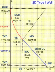
Type 1:
From the Equation 1.1:
Where,
| .0 |
| BUR = 1.50 |
The horizontal displacement is calculated as
Target bearing would be:
Maximum angle of inclination is calculated below:
X = 6.66.deg y = asin y = 27.094 α = X + y α = 33.754 |
Coordinates at Point C can be given as;
| + (Radiu (sin(α)) |
| ( 1 – cos(α)) |
Measured depth at Target point T is given below:
Summary of the results in Tabulated form:
Table 2; Tabulated summary (type I)
| Point | TVD (ft) | Horizontal displacement (ft) | Measured depth (ft) |
| A | 0 | 0 | 0 |
| B | 1650 | 0 | 1650 |
| C | 3772 | 643.89 | 3900 |
| T | 9880 | 4792 | 11370 |
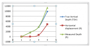
Summary of the results in Graphical form:
Comparison of True vertical depth, horizontal displacement and measured depth:
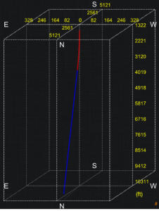
Three dimensional simulation view:
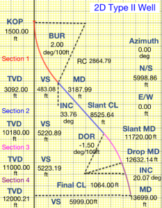
Type 2:
Using the following information, R1 and R2 are calculated as:
From the equations stated in Type II: Build, Hold and Drop Trajectory Plan (b), the following are calculated as:
| OQ = – [( |
OQ = OP = |
OP = 1.081 x 1 QS = QS = 6.685 x PQ := PS := PQ = 1.084 x PS = 8.53 x |
Similarly, the maximum angle of inclination is calculated below:
| X = atan |
| X = |
Y = atan Y = |
| = |
Therefore,
Coordinates at Point C are calculated as:
| : = |
Coordinates at Point D are calculated as:Coordinates at Point E are calculated as:
Measured depth at Target point T is given below:
Summary of the results in Tabulated form:
Table 3; Tabulated summary (type II)
| Point | TVD (ft) | Horizontal displacement (ft) | Measured depth (ft) |
| A | 0 | 0 | 0 |
| B | 1500 | 0 | 1500 |
| C | 3092 | 482.9 | 3188 |
| D | 10180 | 5223 | 11720 |
| E | 11000 | 5522 | 12630 |
| T | 12000 | 6000 | 13700 |
Summary of the results in Graphical form:
Comparison of True vertical depth, horizontal displacement and measured depth:
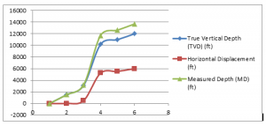
Three dimensional simulation view:
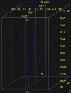
Type 3:
Following the similar pattern and using equation stated in Type III: Continues build Plan (c), and using the following data, the coordinates and angles are calculated as:
And,
R = R = 3.75 x |
Furthermore,
The results in tabulated form are:
Table 4; Tabulated summary (type III)
| Point | TVD (ft) | Horizontal displacement (ft) | Measured depth (ft) |
| A | 0 | 0 | 0 |
| B | 7000 | 0 | 7000 |
| T | 10000 | 1500 | 10480 |
Comparison of True vertical depth, horizontal displacement and measured depth:
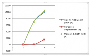
And the graphical form is given as:
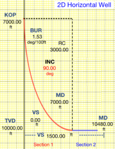
Conclusion
The directional drilling is the science of direction a Well Bore along a predetermined Trajectory to intersect the designated Sub-Surface Targets. Various survey instruments can be used in order to measure the direction of the well bore with reference to the process of selecting most suitable survey techniques, setting up best control tools, finding out applicable administration regulations, and getting relevant geographical data. Various calculation methods can be performed to assure that the design is feasible, for various drilling types, and the designs can be tested using computer simulation tools. Cost estimations can be performed through following various models. Safety aspects of the drilling operations are as important as anything, and must be considered by all means. Wellbore rigs are characterized in accordance with the sire requirements. State of the art tools are available through research and development in the recent past, and can be utilized to gain optimum efficiency of the drilling process.
References
Alpar, C., SNR Technical Instructor, Halliburton-Sperry Drilling: “Directional Drilling” , University of Stavanger, Well Technology Fall 2010, Lecture Notes
A.G. Brooks and H. Wilson, Baker Hughes INTEQ: “An Improved Method for Computing Wellbore Position Uncertainty and Its Application to Collision and Target Intersecting Probability Analysis”, paper SPE 36863, 1996.
B.A. Alidi; H.F. Al-Sarrani ,Saudi Aramco; J. Stewart, Halliburton Sperry Drilling; A. Sarkar; G. Smith, Scientific Drilling: “Use of Gyro-MWD Technology Offshore, A Step Change in Drilling Performance in Saudi Aramco” ,paper SPE 136499, 2010.
Baker H., INTEQ: “Drilling Engineering Workbook”, 80270H Rev. B Dec. 1995.
Bourgoyne, A.T., K.K. Millheim, M.E. Chenevert, and F.S. Young: Applied Drilling Engineering, Society of Petroleum Engineers, Richardson, TX, 2003.
C.J.M. Wolff, J:P. de Wardt: “Borehole Position Uncertainty-Analysis of Measuring Methods and Derivation of Systematic Error Model”, paper SPE 9223, 1981.
C.R. Chia, SPE, Schlumberger; W.J. Phillips, SPE, Schlumberger; D.L. Aklestad, SPE, Schlumberger: “A New Wellbore Position Calculation Method”, paper IADC/SPE 77221,1981.
- Cayeux, Roxar; J.M. Genevois, TotalFinaElf; S. Crepin, TotalFinaElf; S. Thibeau, TotalFinaElf: “Well Planning Quality Improved Using Cooperation between Drilling and Geosciences”, paper IADC/SPE 128299, 2001.
H.S. Williamson, SPE, BP: “Accuracy Prediction for Directional Measurement While Drilling”, paper SPE 67616, 2000.
J.L Thorogood, SPE, Britol PLC: “Instrument Performance Models and Their Application to Directional Survey Operations”, paper SPE 18051-PA, 1990.
Joshi, S.D., “Cost/benefits of horizontal wells,” SPE 83621, SPE Western
Regional/AAPG Pacific Section Meeting, Long Beach, CA, May 19-24, 2003.
L.E. Mahmoud: “Continuous Measurement-While-Drilling Surveying System Utilizing MEMS Inertial Sensors”, department of geomatics engineering, calgary, Alberta, February, 2009
McMillian, W., : “Planning the Directional Well – A Calculation Method,” Journal of Petroleum Technology, 1981; 33(6):952-962
M.J. Kaiser: “A Survey of Drilling Cost and Complexity Estimation Models”, International Journal of Petroleum Science and Technology, ISSN 0973-6328 Volume 1, Number 1 (2007), pp. 1–22
Peterson, S.K., J.A. Murtha, and F.F. Schneider, “Risk analysis and Monte Carlo simulation applied to the generation of drilling AFE estimates,” SPE 26339, Houston, TX, October 1993.
Roger Ekseth: “Uncertainties in Connection with The Determination of Wellbore Positions”, PHD Thesis, ISBN 82-471-0218-8 ISSN 0802-3271, PhD Thesis no 1998: 28
IPT report 1998.2, The Norwegian University of Science and Technology, Trondheim, Norway, March 1998.
Richard S. Carden and Robert D. Grace: “Horizontal and Directional Drilling”, 2007
Richardson, T,: “Applied Drilling Engineering,” Tenth Printing Society of Petroleum Engineers Text , Series, Vol.2, USA, 2005
- Ekseth; E.I Naken; L.K Jensen: “Wellbore Position Calculation Uncertainty-A Tool for Risk Based Decision Making?” Offshore Mediterranean Conference, Ravenna Italy, 19-21 March 1997.
R.P Harvey; J.E Walstrom; H.D. Eddy : “A Mathematical Analysis of Errors in Directional Survey Calculations”, paper SPE 3718-PA.
T.A. Inglis: “Petroleum Engineering and Development Studies”, Volume 2, Directional Drilling, 1987
T.Torkildsen, SPE, Sintef (formerly Statoil); S.T. Håvardstein, SPE, Total; J. Weston, SPE, Gyrodata; R. Ekseth, SPE, Gyrodata: “Prediction of Wellbore Position Accuracy When Surveyed With Gyroscopic Tools”, paper SPE 90408-PA, 2008.
- Garza, SPE; J. Wimberg, SPE, Chevron U.S.A. Inc.; T. Woolridge, Halliburton-Sperry Drilling; E. North, SPE; K. Beattie,SPE, Gyrodata Inc.: “Gyro Guidance Technique and Telemetry Methods Prove Economical in Onshore Multi-Well Pad Drilling Operations in the Piceance basin”, paper IADC/SPE 128299,2010.
T.S. Olberg & H. Laastad, SPE, Statoil; B. Lesso, SPE; A. Newton, Schlumberger: “The Utilization of the Massive Amount of Real-Time Data Acquired in Wired Drillpipe Operations”, paper IADC/SPE 112702, 2008.
T.Torkildsen, SPE, Statoil; S.T. Håvardstein, SPE, Statoil; J.L. Weston, Halliburton Sperry-Sun; R. Ekseth, SPE, Gyrodata: “Prediction of Wellbore Position Accuracy When Surveyed With Gyroscopic Tools”, paper SPE 90408-MS, 2004.
2001 Joint Association Survey on Drilling Costs, American Petroleum Institute, Washington, D.C., December 2002.
Excluded:
Drilling Fluids
Drilling fluids are used for various functions that include removing cuttings from the hole. Careful analyses are required to be performed by the geologists to determine the drilling fluid that best suits local conditions. This fact conditions can change with locations makes the task of selecting drilling fluid as important as anything else. When selecting the drilling fluid, it is crucial to realize its maintenance. It is the duty of both the drillers and the engineers to choose the right fluid as failure to do so can result in a disaster.
The typical features of a drilling fluid are:
- To stabilize the borehole
- Keep subsurface pressure under control
- Provide support to the walls of the borehole
- To suspend drill cuttings in the absence of circulation
- Lubricate and cool the drill string and the bit
- Clean the bottom of the hole beneath the bit
- Transportation of cuttings to the outside
Engineers should be able to minimize the following effects to ensure the drilling fluid can perform its functions successfully.
- The penetration rate must be reduced
- Subsurface formation should be prevented from any damage
- Circulate and clean any pressure problems
- Erosion of the borehole
- Avoid loss of circulation
- The drill pipes should be kept from sticking against the walls
- Keeping any desired solid bits in the drilling fluid to improve chemical properties
- Pump start failures
Following are the characteristics of a good drilling fluid:
- Viscosity
- Velocity
- Lubricity
- Filtrate control
- Gel Strength
- Density
Types of drilling fluids:
Following are the three types of drilling fluids
- Oil based
- Air based
- Water based
According to Akpedeye Kelvin (2010), mud is most commonly used drilling fluid used in today’s petroleum drilling industry. The fact it possesses almost all characteristics of a great drilling fluid makes mud a perfect choice where direction drilling is required to be performed by engineers and geologists. Mud can be categorized as water based drilling fluids. However, several air based and oil based fluids are also employed in some drilling conditions.
Get 3+ Free Dissertation Topics within 24 hours?


