
Proposal
February 16, 2021
Is free trade the best economic policy that countries can adopt or is protectionism ever justified?
February 26, 2021
Introduction
While crossing a bridge, we do not think of the engineering and technical design that goes behind a successful bridge. Bridges provide an important means of transportation, and several factors play a key role in making a bridge successful or collapse. A bridge collapse can result in unavoidable traffic problems and therefore it is vital to identify the design factors that contribute towards a successful bridge design. Some of the most notable engineering projects carried out in the history of the world involved the construction of steel and timber bridges. Although the basics of bridge engineering and bridge design have remained the same for many years, each bridge construction project presents new and sometimes more challenges that must be identified by the engineers to ensure the safety and protection of people crossing the bridge. The geology surrounding the area, the type of materials to be used, the weather and the amount of traffic expected to cross the bridge on a daily or monthly basis are perhaps the most important factors that must be taken into account. Even slightly miscalculating these design factors can result in a disaster (Chatterjee, 1991).
What causes a bridge to collapse?
In this section of the paper, we will briefly look at the factors that result in a bridge collapse. It should be noted that many bridge failures are caused by multiple factors. Poor design combined with natural disasters often leads to a bridge failure. By removing one of these factors, it is possible to maintain the bridge.
Design & Natural factors which can cause bridge failures:
Following are some of the factors that contribute towards a bridge collapse:
- Many engineering collapses were a direct result of manufacturing defects such as the design flaw in steel eye-bars, pillars, decks or years of corrosion worsened to a point where it caused part of a bridge to completely fail.
- A lot of bridge collapses are inevitable not due to natural disasters like earthquakes or floods or manufacturing defects but the bridge design itself. Insufficient strength of materials to support significant loads is one of the most crucial design flaws that should never be overlooked by engineers.
- Inadequate maintenance can also cause a bridge to collapse.
- Earth Quake can result in a bridge collapsing if there is a flaw in the design
- Fire has resulted in a bridge failure in the past. Sometimes a tanker truck containing a large quantity of flammable liquid can trigger an explosion. The bridge can catch fire and the steel deck could melt instantly.
- Train Crash is perhaps the rarest cause of bridge collapses. However, it cannot be completely ignored as there have been such incidents in the past.
- Flood is the most common factor that causes a bridge to collapse. It can make the bridge fail in a range of ways. Floods carrying debris like parts of houses, cars, and trees and the high water smashing against the pillars of a bridge are among the common reasons for failure.
The advancement in technology has provided an opportunity for today’s engineers to estimate the possibilities of the above failure factors, and to consider these while designing the bridge (Demetrios. 1994).
The strength of the bridge lies in the ‘sections’ side of the bridge. Furthermore, long bridges are provided with the support of grounded pillars near the centre of gravity of the bridge’s weight. The bridge must be able to hold its weight as well as the total expected weight of the users. This estimation leads to the calculation of the proposed dimensions/density.
The total design stress of the bridge, which can be defined as the total/maximum load on the bridge per square meter, must be greater than the maximum possible estimated load. For example, the expected load on the bridge is 500 kg/m3, therefore the bridge-designed stress should be greater than this value. The critical value of the failure stress is the maximum limit of the load, or the loading capacity (Lecture notes, 2013).
Design Considerations for Wooden/Timber Bridges and Steel Bridges
The design of the bridge should incorporate all forces and loads that the bridge is likely to experience in its life and therefore there is a need to take into account not only the load of the crossing traffic and the structure but also natural disasters such as earthquakes and floods as mentioned earlier. The loads usually act as a combination of two or more load factors, applied on the surface of the structure simultaneously.
Design Load:
Design load can be defined as the total weight of all the non-structural and structural components of a bridge and deck. This load usually takes into consideration the railing, lines, roadway, sidewalks and other structures attached to the bridge. Wearing surface is also considered one of the components of a bridge when determining the design load. The design load is usually uniform along the length of the component. Dead load is also required to be incorporated in the design load and is normally estimated by the designer.
Vehicle Load:
Vehicle load is the expected load of the vehicles crossing over the bridge. This type of load is variable, which results in varying shears, moments and reactions in the structural elements of the bridge. Vehicle load or forces are usually determined by taking into account the spacing and weights between the loads. The designer must estimate vehicle live loads to calculate the maximum effect of stress.

Figure 1: Steel Bridge (Golden Gate); Steel is utilized for long-distance bridges. Source; 15 Goliath Steel Bridges, www.colorcoat-online.com
Wearing Surface:
The roadway surface is usually placed on the bridge deck and is the only part of the bridge directly in contact with the vehicles crossing over the bridge. A wearing surface is one of the most important design factors for a wooden or timber bridge, mainly because of the fact it enhances the overall skid resistance and ensures a safe and smooth surface for traffic passing over a bridge. Without a well-designed wearing surface, a wooden or timber deck can deteriorate very quickly, resulting in inadequate structural capacity.
The design of a wearing surface depends on several factors including the volume and amount of traffic, maintenance and construction costs as well as the weight of the traffic expected on the bridge.
Dynamic Effect:
The dynamic effect includes the increased stresses applied on the bridge due to moving vehicles. It should be noted that the stress produced by the same loads applied statistically will be significantly lower. Longitudinal force, Centrifugal Force, Wind Load, Thermal Force, Uplift, Earth Pressure and earthquake forces are other loads that should be considered when designing a wooden or timber bridge (Bamhart, 1986).
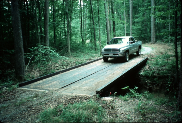
Figure 2: Wooden Bridge; Wood/Timber is utilized for small bridges (low stress/load). Source: Timber Bridges Las Vegas, www.flickr.com
Conclusion
The total expected load in any bridge can be estimated using various methods. This load can then be analysed to calculate the total stress on the bridge. The critical stress point/failure stress can then be compared with these values to ensure that the bridge does not fail and is safe. The centre of gravity is the point where the stress is at its maximum. The stress structure is analysed to obtain the support requirements for successful bridge operations. Exceeded tensile strength causes the bridge failure. The maximum load on the bridge can be calculated/attained by multiplying the cross-sectional area with the tensile strength. The reliance on the bending strength to support the load (s) is not considered in the design of the bridge. Assuming that the joints are not supported with bending loads; then it can be concluded that the forces acting on the bridge are compression and/or tension only, and these forces act in the directions of the associated beams.
References
American Society of Civil Engineers, (1980). Loads and forces on bridges.
Bamhart, J.E., (1986). Ohio’s experiences with treated timber for bridge construction. In: Trans. Res. Rec. 1053. Online information at: http://trid.trb.org/view.aspx?id=276764
Chatterjee, S.M (1991). The Design of Modern Bridges, First edition, BSP Professional books
Owens. G.W., Knowles. P.R., Dowling. P.J.,(1994). Steel Designers' Manual, Fifth edition, Blackwell Scientific Publications.
Demetrios. E.T., (1994). Design, Rehabilitation and Maintenance of Modern Highway Bridges, McGraw-Hill Publishers.
Loads and forces on timber bridges. Chapter 6. Available online at 6 http://www.dot.state.mn.us/bridge/documentsformslinks/inspection/usfs-timberbridgemanual/em7700_8_chapter06.pdf [Retrieved on 10 October 2013]
Steel bridge design handbook, 2012. Bridge Deck Design publication no. fhwa-if-12-052 – vol. 17 November. Available online at: http://www.fhwa.dot.gov/bridge/steel/pubs/if12052/volume17.pdf [Retrieved on 10 October 2013]
Wearing surfaces for timber decks, Chapter 11, Available online at: http://www.dot.state.mn.us/bridge/documentsformslinks/inspection/usfs-timberbridgemanual/em7700_8_chapter11a.pdf [Retrieved on 10 October 2013]
Success and failure aspect of bridges