
Green Infrastructure
February 27, 2021
Carbon Trading: A Solution to Global Warming?
February 27, 2021
It has been proposed to construct a nine-storey four-star hotel in the locality of the Ealing Town centre. It has been proposed that the hotel must be facilitated with all the basic requirements of standard 4-star hotels, including a children’s play area, and a car park and it must be landscaped for boulevard frontage.
The construction of any commercial building requires numerous high-profile engineering tasks, which will be briefly discussed in this report. Engineering details and specifications, construction plan and design layout are also provided in this report.
The site chosen for the construction of the project is centrally located and the schemes presented blend with the purpose of the hotel. The site is located north of Uxbridge in the Ealing Town Center. The site front’s onto the main Uxbridge Road – A4020, and borders along the rear Craven Avenue residential property. The total site area is estimated to be 3346 m2, which is 34 m long from the front and 105 m in long depth.
In order to successfully develop and construct the required building, a careful study must be undertaken to analyze the key resourceful/facilitating parameters involved in the project. This includes the ease of access to the site, commercial and retail requirements of the users, transportation links and car parking. For a four-star commercial facility, special consideration must be given to the following;
- The site area must have sufficient lighting, especially in the car parking and entrance roads/paths
- The design of the complex must be safe and secure, a commercial building which is expected to host a large number of occupants must comply with the safety and security regulations. For example, sufficient emergency exits and fire prevention facilities must be provided under the law
- Measures of Crime prevention must be accommodated. A four-star building must be designed in such a way that primary crime prevention measures can be easily taken.
Various other influential factors must be considered, however presenting these consideration is out of the scope of this report.
Chapter – 2; Site Layout Plan
The proposed hotel will need to be accommodated with the following built-in facilities;
- A central lobby, various cafes, a central bar, and administrative facility centres
- A 200-300 seat central restaurant on the ground floor
- Single and double bed deluxe rooms
- Sports centre/facility which would include changing room, comprehensive gym, multiple showers, sauna and/or steam room, and swimming pool
- Boiler and air handling unit room for HVAC
- Various shops
- Security and surveillance offices
In order to provide the above facilities, the following works will be required to be completed;
- Electrical wiring works, in accordance with the required electrical capacity.
- Water pipeline distribution system and sewerage water collection system
- Gas pipelining
- Central HVAC lining and diffusing system to provide regulated/controlled air supply (both hot and cold)
- Water reservoir, to provide approximately a week’s supply of water through water pumps. This system can also be utilized to provide emergency water through fire hydrant systems
- Power supply lines or power generation system
- Safety and fire, protection system
- Security system, walled perimeters, in and out gates, and guard-houses
- IT and communication systems
The following figure presents the preliminary outline of the proposed site;
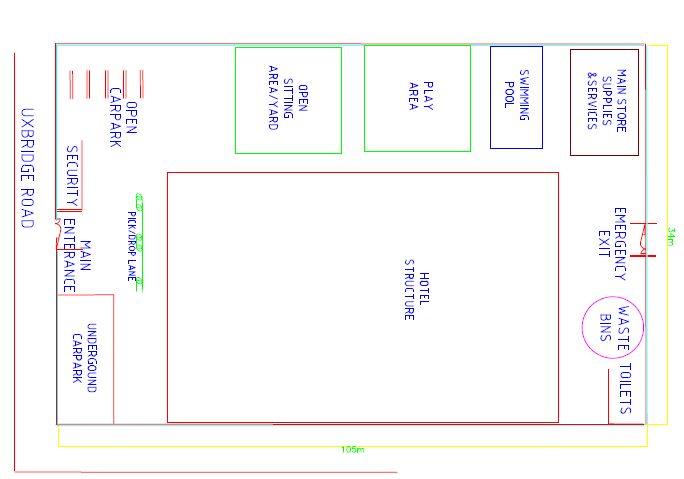
Figure-1: Site Layout (footprints, AutoCAD)
Figures-1 have been developed to show the comprehensive site outline with respect to site footprints. It will have all the required facilities which must be available in a standard 4-star Hotel. It is accompanied by the children's play area, extensive sitting lounge and car parks. The hotel is designed for an extended ground floor lobby so that the visitors/residents can be provided with all the luxuries facilities such as cafes, dining halls etc. Two entrance door and a specific exit door at the back of the building has been provided to assure that sufficient exits are available for an emergency case.
The layout of the pan from the 2nd floor to the 9th floor will have up to 50 deluxe rooms. It has been planned to have these rooms constructed through the drywall partitions using the gypsum board-wide tiles. These systematic partitions will be installed using the steel frames, which would allow easy to install partitioning system. This would also ensure that if in future the plan has to be changed/re-arranged, the partition could be removed and re-installed in accordance with the required plans.
Chapter – 3; Site Waste Management Plan and Environmental Constraints
According to the latest legislation of Aril, 2008, the Site Waste Management Plan (SWMPs) has been made mandatory for all construction-related projects in the United Kingdom, specifically the projects which are worth greater than three hundred thousand pounds, excluding taxes. This act has been justified as the waste management plans can support the construction industry in the form of maximizing taste utilization and reduction in the mismanagement of the waste produced on the site.
The waste management plan detailed in this section outlines the estimated/expected amounts and types of waste generated on the construction site. The waste on site can be accumulated through both waste generations during construction and also through the processing of the imported materials which are to be used on the site. The imported materials are used/installed on the structure of the proposed building. General waste is also generated through the demolition works, or these already exist on the project such as sob soils, top-soils and trees (Wayne and Trusty, 2007).
The primary considerations undertaken for the waste management on the site include possibilities of waste reduction, waste segregation and waste disposal. Financial impacts are not considered since this is out of the scope of this paper.
The Expected/estimated Volumes in m3 of Waste to be generated on-site are tabulated as below;
Table-1; Waste Estimates
|
|
Type of Waste |
|
Imported/ General/Demolition waste |
|
Waste during/through Construction works |
|
||||||
|
|
|
|
|
|
|
|
|
|
||||
|
|
|
|
|
|
|
Approximate Quantity in m3 |
|
|
|
Approximate Quantity in m3 |
|
|
|
|
|
|
|
|
|
|
|
|
|
|
|
|
|
|
|
|
_ |
|
|
|
|
_ |
|
|
|
|
|
|
|
|
|
|
|
|
|
|
|
|||
|
|
Inert Waste Types |
|
|
|
|
|
|
|
|
|
|
|
|
|
Rocks |
|
|
|
|
|
|
|
|
|
|
|
|
|
Gravels |
|
|
|
|
|
|
|
160 |
|
|
|
|
|
Cumulative Sand |
|
|
|
|
|
|
160 |
|
|
||
|
|
Concrete |
|
|
|
|
|
|
180 |
|
|
||
|
|
Aggregates |
|
15 |
|
|
90 |
|
|
||||
|
|
Blocks |
|
|
|
|
|
|
90 |
|
|
||
|
|
Bricks |
|
|
1000 |
|
|
|
200 |
|
|||
|
|
Top-soil (not contaminated) |
|
20 |
|
|
8000 |
|
|||||
|
|
Sub-soil (contaminated) |
|
|
|
|
|
|
5000 |
|
|
||
|
|
Excavated bulks (not contaminated) |
|
|
|
|
|
|
|
|
|
|
|
|
|
|
|
|
|
|
|
|
|
|
|
|
|
|
|
Glasses |
|
|
|
20 |
|
|
|
|
|
|
|
|
|
Polyesters |
|
|
|
|
|
|
20 |
|
|
||
|
|
Non biodegradable Plastics) |
|
|
|
|
|
|
|
|
|
|
|
|
|
Sub-TOTAL |
|
|
|
|
|
1055m3 |
|
|
|
13880m3 |
|
|
|
Waste considered as biodegradable |
|
|
|
|
|
|
|
|
|
|
|
|
|
Plaster-boards |
|
2 |
|
|
15 |
|
|
||||
|
|
Products of gypsum |
|
|
|
|
|
|
|
|
|
|
|
|
|
Accumulated Metals |
|
|
|
|
|
|
40 |
|
|
||
|
|
Timber (from frames and other) |
|
3 |
|
|
120 |
|
|
||||
|
|
Card-board |
|
|
|
|
|
|
15 |
|
|
||
|
|
Paper |
|
|
|
|
|
|
|
10 |
|
|
|
|
|
Plastic |
|
|
|
|
|
|
5 |
|
|
||
|
|
Accumulates Tress |
|
|
|
|
|
|
40 |
|
|
||
|
|
Trees |
|
10 |
|
|
5 |
|
|
||||
|
|
Sub-TOTAL |
|
|
|
|
15m3 |
|
|
|
255m3 |
|
|
|
|
Contaminated/Hazardous Wastes |
|
|
|
|
|
|
|
|
|
|
|
|
|
Sub soil and Top-soil |
|
|
|
|
|
|
|
|
4 |
|
|
|
|
Sub soil (contaminated) |
|
|
|
|
|
|
|
|
|
|
|
|
|
Waste through Excavation |
|
|
|
|
|
|
|
4 |
|
|
|
|
|
Other (flammables/toxic/explosive) |
|
|
2 |
|
|
|
|
|
|
||
|
|
Sub-TOTAL |
|
|
|
|
2m3 |
|
|
|
8m3 |
|
|
|
|
TOTAL |
|
|
|
|
|
1072m3 |
|
|
|
14143m3 |
|
|
|
|
|
|
|
|
|
|
|
|
|
|
|
|
|
||||||||||||
One of the key factors considered to be highly important for good waste management is setting the priorities for the accumulated wastes. Following is the waste priority list generated for the completion of this project
- Concrete; considered to be inert, originated through the demolition process and site strip
- Tarmac; considered to be inert, originated through site-strip
- Bricks and large blocks; inert, mainly originated through site-strip and demolition works
- Timber; biologically active, mainly originated through site-strip
- Metals; reactive, originated through the demolition process and site-strip
- Plasterboards; biologically active, mainly originated through the demolition process
In order to minimize the waste generate on-site, effort shall be made from the very beginning of the project to reduce the total amount of expected waste generation. The waste minimization efforts will be encouraged by advising the project contractors, designers, and suppliers to reduce waste by doing the best possible methods of waste reduction. To further enhance the process, a waste management committee will be prepared which will look into all the waste management practices being followed. The site manager, the construction manager, the foreman and the design team will take responsibility for task.
The process of segregation is planned to be conducted through facilitating the material separation process, which would potentially highlight the recyclable and re-usable materials. This will have a positive impact on the financial and environmental aspects of the project process. The designated location will be assigned for the materials collected as recyclable and reusable, such as Metals, wood, bricks and timber. In the following table, the waste is mainly characterized as (1) reusable, (2) recyclable and (3) landfill. The management of waste disposal will be based upon these three main waste types
Table-2; Waste Management
|
Types of waste |
Action |
|
|
Imported/ General/Demolition waste |
||
|
1. |
Concrete |
Reuse mainly onsite |
|
|
|
|
|
2. |
Tarmac |
Reuse mainly onsite |
|
|
|
|
|
3. |
Bricks and Blocks |
Reuse mainly onsite |
|
|
|
|
|
4. |
Timber |
Recycle off site |
|
|
|
|
|
5. |
Sub-soils |
Reuse mainly onsite |
|
|
|
|
|
6. |
Metals |
Send for reuse off site or recycle |
|
|
|
|
|
7. |
Asbestos |
No usage |
|
|
|
|
|
8. |
Plasterboard |
Recycle, or landfill if not recyclable |
|
|
|
|
|
Construction Works
|
||
|
1. |
Plasterboard |
Recycle, or landfill if not recyclable |
|
|
|
|
|
2. |
Bricks/Blocks |
Recycle off site |
|
|
|
|
|
3. |
Timber |
Recycle off site |
|
|
|
|
|
4. |
Cardboard |
Recycle off site |
|
|
|
|
|
5. |
Metals |
Recycle off site |
|
|
|
|
|
6. |
Paints |
Recycle where possible or landfill |
|
|
|
|
|
7. |
Soils |
Recycle off site |
|
|
|
|
The best possible waste management techniques eventually have a positive environmental impact. The environmental management system requires the demonstration of healthy environmental performances throughout all the activities undertaken during the construction project. Therefore, environmental impacts have been given primary consideration in this project; which can be recognized choice of in materials to be used for the construction process and the waste management practices (Norgate, et al., 2007).
Strict mitigation measure will be taken to ensure the surrounding habitats are protected and there is no adverse effect to the surrounding environment during construction. The measure will include control of both airborne-pollutants (through vehicle control, burning on site prevention etc.) and waterborne-pollutants (through awareness of ecological constraints, drainage channels and silting/erosion control). A Standard control system of pollution control will be implemented for this construction project which would include general potential impact, pollution of water courses; through concrete etc and vibration and noise pollution; through use of heavy equipment. The mitigation measure will help protect such impacts.


Chapter – 4; Project Construction Schedule
Construction scheduling is considered to be one of the primary requirements for successfully completing the construction project. The project construction schedule outlines the main activities to be undertaken from the concept/design to its completion. The table below shows the plan of construction in terms of schedule; starting from the site preparation stage and finishing the building structure.
Table -3; Construction Program for project completion (Major tasks identified)
|
Year |
2014 |
2015 |
|||||||||||||||||||||||||||||
|
Month |
02 |
04 |
06 |
07 |
08 |
09 |
10 |
11 |
12 |
01 |
02 |
03 |
04 |
||||||||||||||||||
|
Weeks |
08 |
16 |
24 |
28 |
32 |
36 |
40 |
44 |
48 |
52 |
56 |
60 |
64 |
||||||||||||||||||
|
|
|
||||||||||||||||||||||||||||||
|
|
|
||||||||||||||||||||||||||||||
|
Site Preparation |
|
|
|||||||||||||||||||||||||||||
|
Arrangement of Transportation and import of materials on site |
|
|
|
||||||||||||||||||||||||||||
|
Site excavation process including for the underground car park |
|
|
|
||||||||||||||||||||||||||||
|
Pilling- caps – beams including basement |
|
|
|
||||||||||||||||||||||||||||
|
Pilling for foundation- fill by concrete for foundation development |
|
|
|
||||||||||||||||||||||||||||
|
Steel structure construction and rafting slabs over the piles |
|
|
|
||||||||||||||||||||||||||||
|
Other civil works for structural framework development |
|
|
|
||||||||||||||||||||||||||||
|
Floorings-slabs; starting from the basement |
|
|
|
||||||||||||||||||||||||||||
|
Floor constructions all floors |
|
|
|
||||||||||||||||||||||||||||
|
Roofing for all floors |
|
|
|
||||||||||||||||||||||||||||
|
Base and bindings |
|
|
|
||||||||||||||||||||||||||||
|
Completion of frame work and concrete |
|
|
|||||||||||||||||||||||||||||
Chapter – 5; Earth Work Calculations and Mass Haul Diagram
A new road of 100 meters of length is to be constructed through the length of the site, for which the table below shows volumes of cut (+ve) and fill (-ve) for each 10m length required for construction of a new road. The shrinkage factor of 0.8 has been considered to perform the earth work calculations (for positive volumes), and the Mass Haul Diagram was prepared using the results obtained (Lecture Notes, 2013).
Table -4; Earth Work Calculations
|
Chainage (m) |
Volume (m3) |
Cut(+ive) |
Fill(-ve) |
Shrinkage factor |
Equivalent volume (shrinkage x volume) |
Cumulative volume |
|
0-10 |
20 |
+20 |
|
0.8 |
16 |
16 |
|
10-20 |
48 |
+48 |
|
0.8 |
38.4 |
54.4 |
|
20-30 |
20 |
+20 |
|
0.8 |
16 |
70.4 |
|
30-40 |
-30 |
|
-30 |
1.0 |
-30 |
40.4 |
|
40-50 |
-38 |
|
-38 |
1.0 |
-38 |
2.4 |
|
50-60 |
-32 |
|
-32 |
1.0 |
-32 |
-29.6 |
|
60-70 |
-28 |
|
-28 |
1.0 |
-28 |
-57.6 |
|
70-80 |
-12 |
|
-12 |
1.0 |
-12 |
-69.6 |
|
80-90 |
-5 |
|
-5 |
1.0 |
-5 |
-74.6 |
|
90-100 |
15 |
+15 |
|
0.8 |
12 |
-62.6 |
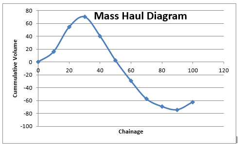
Figure-2: Mass Haul Diagram for Road Construction
Chapter – 6; Investigation and Justifications
Foundation:
For the construction of the Hotel, deep foundations will be constructed in order to share the load of the structure. Deep foundations are considered to transfer the overall/total load of the structure to the bearing ground at a specified depth below the surface/ground level. The primary components to be used for the foundation are piles and pile caps. The pile columns are constructed below the surface level to provide foundational support to the hotel structure as the ground may not provide sufficient support for the nine story building. These piles provide resistance to the vertical, lateral and uplift loads. Large diameter bored piles will be used in our project, since these are best suited for the construction of large buildings which are expected to be under heavy loads. The bored piles are considered to cope with heavy loads, and the larger diameters of the piles will provide the benefit of consuming fewer piles in group. However, this foundation will required extensive excavation process.
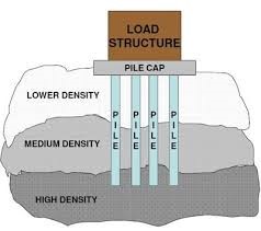
Figure-3: Deep foundation Piling (source: Pile Foundations, 2013)
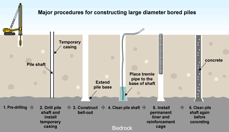
Figure-4: Major construction procedures for large bored piles (source: Icac, 2013)
Basement
The basement is to be constructed for the use of an underground car park, located below the main entrance of the Hotel. A full/complete basement below the ground floor of the Hotel has not been planned / designed as the 9 floored building is sufficient for the user requirements. Furthermore, adding the basement of Grade 3 (BS 8102:2009) basement would have added huge cost to the project.
A Grade 1 basement is to be constructed through supporting structure of Diaphragm walls, as these can provide rigid wall at considerably lower price. These are best utilized for large and open sites, which one of our project requirements. These are to be constructed through the use of reinforced concrete by the under slurry technique; which involves excavation of narrow trench and filling it with the processed fluid of concrete solution. Basement wall to be constructed is expected to be very stiff, and therefore higher level of deflection resistance will provided to the basement structure. The Top-down conventional construction technique will be utilized for the construction of the basement, and the process will be initiated as the excavation is progressed. This construction method will be provide considerable saving of the time, and hence the cost. The steel beams will be used to provide support to the basement columns. The procedures of construction include; retaining wall construction, construction of piles followed by stage wise excavation and casting of floor slabs.
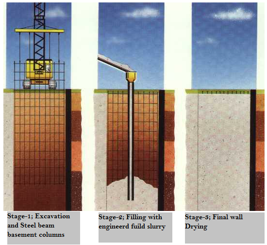
Figure-5-: Basement construction procedure (source: edited, lecture notes, 2013)
Structural frames
The Steel Frame structure will be used for the construction of the Hotel. The steel frames offer various advantages over other frames (Mangena and Brent, 2006). The steel framed structure has been selected due to the following reasons;
- The steel frames can be produced over a shorter period time due to their offsite pre-fabrication
- The steel frames are considered to be constructed with enhanced safety, high quality and cost effectively
- The structure steel works and activities can be completed at shorter time, which reduces the total cost of the project
- The steel frames offer wide spanned structural frames works, which is best suited for our project of Hotel construction as the column free wide structure are provided. The Steel frames further offer floor layout flexibility
- One of the more important factors considered while selecting the frame work type was the environmental influence and sustainability. Steel frames are considered to be fully recyclable without compromising on quality. Even after full life passage of the structure, up to 86% of the steel frames can be recycled.
- Sound transmission if another important factor with respect to Hotel management, as sound transmission must be avoided with the building partitions. Steel frames lack in this quality, however with well managed sound proofing systems and impact sound reduction systems, this issue will be resolved
- Extra caution will be taken to fire proof the building as there is a risk of steel softening when exposed to very high temperature. This will be resolved through application of passive fire protection system such as fire proof coating and spray.
The Steel structure framework will be added with the flooring slabs constructed from the pre-cast concrete, with the steel angles adjacent supports. The steel structure will be coated with the surface coating to have it protected from any possible corrosion
Chapter – 7; Conclusion- Reflection and Evaluation
Through research conducted and assessment studies completed for the completion of this report, it was found that the completion of a multi storey building involves multiple aspects which must be considered by the design and engineering teams. The purpose of the construction is the key parameter which drives the design procedures. The requirements of the building and the associated required facilities are outlined, and the layout is prepared. Once approved, various other engineering activities are initiated. Almost every activity involved in the project is critical; therefore highly efficient management system is absolutely necessary for the successful completion of the project
The site chosen for the construction of the nine storey building must be feasible in terms of the locality of the subject area; the business of the Hotel operations can have a huge influence due the locality and therefore the feasibility survey/analyses must be completed. Once the site is chosen, it is important that all the aspects of the processes such as design, construction, waste management, facilities provisions, materials to be used, supports and structure types etc are carefully considered. The process normally starts with site preparations and ground analyses, and ends with the finishing of the complete structure.
Factors such as project scheduling in terms of the main activities to be undertaken, selecting the structure, foundations types, and the materials management have been found to be critical in the study completed. For this project, Steel frame has been selected to structure the building, mainly due to its environmental potential, high level load capability and ease of installation. The waste management was also planned such that the high efficiency could be attained. The design further highlighted that that the use of the earth work calculation and the mass haul diagrams can prove to be useful for the planning, construction and future development works
The overall layout and the design presented in this report was prepared considering all the factors stated above, and the every effort was made to ensure that all the requirements both in terms of facilities and engineering are provided. It is also important to note that detailed analyses have been completed due the limited scope of this work; therefore it is recommended to further study this design and prepare the detailed documentation for the project including the specification details.


References
BS 8102, 2009. Code of practice for protection of below ground structures against water from the ground. ISBN 978 0 580 59399 4, pp. 4-42
EN 1994-1-1:2005: General rules and rules for buildings
EN 1994-1-2:2008: General rules. Structural fire design
EN 1991: Eurocode 1 Actions on structures. General actions
Icac, 2013. Large diameter bored piles. Available online at: http://www.icac.org.hk/new_icac/eng/cases/piling/p04c.html. [Retrieved 09 December 2013]
International standardization organization 2006. Environmental Management, Life cycle assessment – Principles and framework. ISO14040
Johns, W.R., Kokossis, A., and Thompson, F., 2008. A flow-sheeting approach to integrated life cycle analysis. Chemical Engineering and Processing 47: 557–564.
Krozer, Y., 2008. Life cycle costings for innovations in product chains. Journal of Cleaner Production 16: 310-321.
Lecture Notes, 2013. Semester 1, Civil Engineering Construction, Semester 1, University of West London pp.2-84
Mangena, S.J., and Brent, A.C., 2006. Application of a Life Cycle Impact Assessment framework to evaluate and compare environmental performances with economic values of supplied coal products. Journal of Cleaner Production
Norgate, T.E., Jahanshahi, S, and Rankin, W.J., 2007. Assessing the environmental impact of metal production processes. Journal of Cleaner Production 15: 838-848.
Pile Foundations, 2013. Available online at: http://kekanaan.wordpress.com/2013/11/13/pile-foundations/ [Retrieved 09 December 2013]
New Zealand Green Building Council (NZGBC) 2008. Technical Manual Office Design Tool Version 1. pp vi.
Smith, A. L., Hicks, S. J. and Devine, P. J., 2008. Design of floors for vibration: A new approach
Steel Buildings in Europe, Multi-storey steel buildings, 2013. Parts 2, 5 and 5: Concept design, Joint design and Actions. Available online at: www.access-steel.com [Retrieved on 26 November 2013
Steel Building Design, 2009. Design Data The Steel Construction Institute, P363
Wayne, B., and Trusty M.A. 2007. Integrating LCA Tools in Green Building Rating Systems. Sustainable Materials Conference, Vancouver. Sustainable Materials Institute, Ontario. Pp112-113.
Get 3+ Free Dissertation Topics within 24 hours?
Assignmnet-2 BEng/FdEng Civil & Environmental Engineering