Simulation of Vehicle Performances with Different Power Systems
February 1, 2021
The Impact of Technology in Improving Resilience and Sustainability in Construction Projects – Case of BIM and LCA
February 4, 2021Abstract
This section will be a brief summary of the dissertation and research project. The abstract will be created in an effort to help the reader quickly understand the purpose of the paper.
Acknowledgements
The Acknowledgement section will provide a statement of appreciation and gratefulness to contributors for their help to the researcher in completing the project.
Research questions:
Following are the main research questions of this research paper:
- What is a pneumatic conveying system? How does it work?
- A brief background of pneumatic conveying system and the equipment used to ensure efficient handling of the process as well as meeting output requirements?
- What are the main types of pneumatic conveying system, how can one categorize them? What are their respective applications? Limitations?
- What are the characteristics of cement and coal for a pneumatic conveying system?
- How the process safety and reliability can be improved?
- What are the key parameters that must be controlled to improve process efficiency and safety?
- What could be the influence of the powder type i.e. cement and the factors impacting the powder?
- What are the components of a testing rig and how the rig is directly related to the performance characteristics of a pneumatic conveying system?
- How the challenges in the new world can be overcome?
- Recommendations for future work?
Aims and Objectives
The purpose of this project is to develop complete understanding about the pneumatic conveying system and the variables that are required to be controlled to ensure soothe operations, process safety and reliability. The aim of this research is to look into pneumatic conveying system analyses/operations, and the industry’s best practices and other complex operations to enhance and the safety and reliability of pneumatic conveying system. Summarizing, the methodology and design of the system will be analyzed in detail in terms of operations, development, safety and dependability. Furthermore, there will be discussion about how the technology can be improved by employing state of the art techniques.
From the Design Guide of the pneumatic convening, an introduction regarding the operation will be presented, including theoretical relationship between the powdered mass weight and the air flow rate (D. Mills, 2004).
Chapter 1-Introduction
The process by which bulk material is transferred using the gas medium as the transfer source is called pneumatic conveying system. Air is considered the most common gas source used as the transfer medium, however other gases can be used to transfer the bulk material where dust hazard such as dust explosion exist.
The pneumatic conveying systems are considered to more viable option to transfer the materials as compared to other methods such as belt, screw and vibrating conveyers. This is because the pneumatic systems are more economical in operations and as well in installations. There are less mechanical systems (moving parts) required in pneumatics systems, and this system is more environmentally friendly due to the source of energy used. Furthermore, these systems are easy expandable, if required, and are easy to maintain
The pneumatic conveying system used to study and research in this paper is shown in the figure below.
Chapter 2; Roads
Introduction
The construction of roads can be defined as of preparing a hard surface for the travellers by overcoming any obstacles in the right of way, in consideration with state of law. The process of road construction starts with the design of road patterns best suited for residents with respect to their travel needs. The first step taken during the construction phase is removal of earth rocks by digging, before laying on the pavement and road building equipments materials.
Once the design and environmental and legal issued are approved/considered, the road alignments are finalized by the civil works team management; the design gradients and radii of the road are set to as per best fit methods with respect to the site ground levels. This activity ensures minimize cut and fill for civil works and enhances diver’s safety.
Roads are primary constructed for the use of motor vehicles and pedestrians. Therefore, rain storm drain systems along with other environmental impacts are considered as a major parameters in the road designs. Sediment, erosion and other control systems are built to neutralize detrimental-effects. Drain lines are constructed all the way along the road to assure storm water is collected safety at the nearest sewerage system. The Darin lines are built in road-easements with the joined seals to ensure smooth flow of water. This system needs approval by the local development authorities, to guarantee that the design flow is good enough for the actual drainage system.
Road Construction Process
The following processes are taken during the construction of roads;
- Excavation
- Filling
- Compacting
- Construction
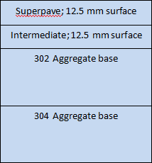
Roads are constructed of various layers of asphalt and aggregates. Excavation is carried out to remove low compact and unrequited material from the land / site, and the moisture content is balanced as per designed value. This is then compacted with standardized fill with relative compact percentage of 85-95. This process is completed by the compacted layer method, in which the fill layer is spread along the designated area and its is then compacted through heavy weight machinery. The fill – compaction process is undertaken until the desired specifications of the road are achieved. Following is an example of road material specification details, provided by the road construction agency in UK. The thickness of layers may vary depending on the specifications of the heavy traffic and native soil


Figure 1; Details of Material specifications with respect to layers
The fill material used for the road construction is without any organic material and has the desired/designed stress bearing ratio and minimum plasticity index. The aggregate base mixtures is generally comprised of a mixture of sand and very fine gravel, which helps to maintain the bottom surface free from any organic matter growth such as plants and serve as lower stratum drainage.
The next layer fill is composed of broken rocks, gravel and /or sand clay of certain sizes as shown in the figure 1 above. The road-bed is rolled for each layer of fill, which compacts the fill and normalization the particulate distribution throughout the road.
Various pavement layers are used to improve quality of the road. These pavement layers consist of geosynthetics which are of extreme importance with respect to improving quality of the roads. These geosynthetics help to increase the road/layer strengths, enhances reinforcement attributes, drainage and filtration. Therefore, pavement performance is optimized with respect to overall construction, decrease in costs and maintenance
The road final finishing is done by paving. The road surface is finalized after having considered factors such as expected usage and other economic factors.
Road pavement design criteria
This section provides technical details of a standard pavement design criteria for road constructions. The design criteria can be set for twenty years of pavement life provided that the maintenance work is carried out to maintain the road surface after completion of the road. Equivalent Daily Load application and Design Traffic numbers are considered in the design calculation for the roads. The following classifications can be considered as minimum limits for pavement sections during the design of the roads. Final designs should be based on real site test results for sub grade support
Table 1; Pavement design classifications
Classification | Equivalent Daily Load application | Composite Section Asphalt | Composite Section Stabilised sub grade or base course | Full depth asphalt | Cement concrete |
Local | 8. 0 -- 10. 0 | 3. 0” | 6. 0” | 5. 0” | 6. 0” |
Residential Commercial | 10. 0 100. 0 | 3. 0” 4. 0” | 6. 0” 6. 0” | 5. 0” 6. 0” | 6. 0” 6. 0” |
Arterial | 200. 0 | 5. 0” | 6. 0” | 7. 0” | 6. 5” |
Arterial (major) | 200. 0 | 5. 0” | 6. 0” | 8. 0” | 6. 5” |
Excavation requirements
Moisture conditioned fill is put in to replace the expansive soil sub-grades. Expansive Soil sub excavation requirements are as follows;
Table 2; Excavation requirements
Plasticity Index | Fill Treatment Local | Fill treatment Arterials |
15 – 20 20 – 30 30– 40 | 1.0 foot approx 2.0 feet approx 3.0 feet approx | 2.0 feet approx 3.0 feet approx 4.0 feet approx |
Get 3+ Free Dissertation Topics within 24 hours?


